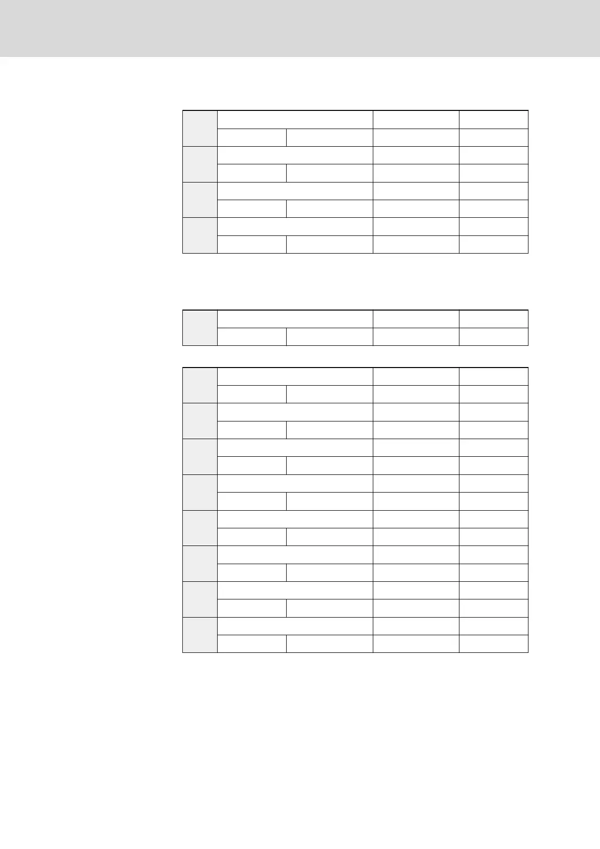
Group E5: Extended parameters
E5.00
VR3 channel amplification factor k4 Factory default 1.00
Setting range 0.00...10.00 Minimum unit 0.01
E5.01
Pulse input filtering time Factory default 0
Setting range 0...9 Minimum unit 1
E5.02
Reserved Factory default 0
Setting range 0, 1 Minimum unit 1
E5.03
Reserved Factory default 0
Setting range 0, 1 Minimum unit 1
● E5.01 is used to define the pulse channel filter time constant for pro‐
cessing of input signals. Longer filtering time means stronger anti-inter‐
ference capability and slower response; shorter filtering time means
weaker anti-interference capability and faster response.
E5.04
Relay outputs Ta, Tb and Tc Factory default 12
Setting range 0...14 Minimum unit 1
See descriptions of parameters E1.00...E1.02.
E5.05
FM1 output lower limit Factory default 0.0
Setting range 0.0 %...[E5.07] Minimum unit 0.1
E5.06
Output corresponding to [E5.05] Factory default 0.00
Setting range 0.00...10.00 V Minimum unit 0.01
E5.07
FM1 output upper limit Factory default 100.0
Setting range [E5.05]...100.0 % Minimum unit 0.1
E5.08
Output corresponding to [E5.07] Factory default 10.00
Setting range 0.00...10.00 V Minimum unit 0.01
E5.09
FM2 output lower limit Factory default 0.0
Setting range 0.0 %...[E5.11] Minimum unit 0.1
E5.10
Output corresponding to [E5.09] Factory default 0.00
Setting range 0.00...10.00 V Minimum unit 0.01
E5.11
FM2 output upper limit Factory default 100.0
Setting range [E5.09]...100.0 % Minimum unit 0.1
E5.12
Output corresponding to [E5.11] Factory default 10.00
Setting range 0.00...10.00 V Minimum unit 0.01
Used to define the relationship between the outputs set by E1.10 and E1.13,
and the corresponding analog outputs.
● When the outputs exceed the upper or lower limit, the frequency con‐
verter will output the voltage corresponding to the upper or lower limit.
● When output current signals are activated, 1 mA represents 0.5 V.
Bosch Rexroth AG DOK-RCON02-FV*********-IB08-EN-P160/259
Rexroth Frequency Converter Fv
Parameter Settings