PZD process data area
When the master is sending a request message to the slave, PZD1 and
PZD2 in PZD process data area are respectively corresponding to control
word (CW) and reference frequency (REF) and PZD3...PZD10 (number de‐
pending on PPO type) are written as 0. When the slave returns a response
message to the master, PZD1 and PZD2 in PZD process data area are re‐
spectively corresponding to status word (SW) and actual output frequency
(ACT), and PZD3...PZD10 are corresponding to status monitoring values
(such as output current, output voltage, AC bus voltage, etc.) set by function
code parameter H0.04 to H0.07.
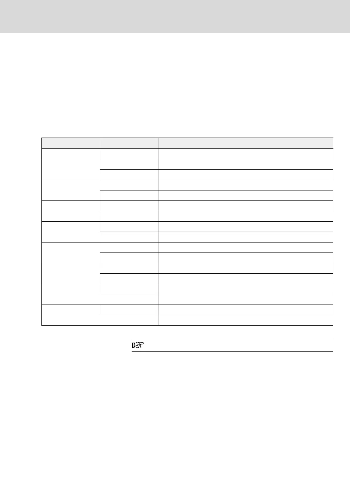
● Control word (CW)
bit Value Description
15...8 – Reserved
7
0 Control active
1 Control inactive
6
0 Inactive
1 SCI stop acceleration/deceleration
5
0 Fault reset inactive
1 Fault reset active
4
0 E-Stop inactive
1 E-Stop active
3
0 Inactive
1 Stop as parameter setting mode
2
0 Forward
1 Reverse
1
0 Jog inactive
1 Jog active
0
0 Run inactive
1 Run active
Tab. 12-37: bit definition of control word
When bit7 is 1, command is invalid.
DOK-RCON02-FV*********-IB08-EN-P Bosch Rexroth AG 241/259
Rexroth Frequency Converter Fv
Communication Protocols