Dimensioning variables of the table values
1. Installation types:
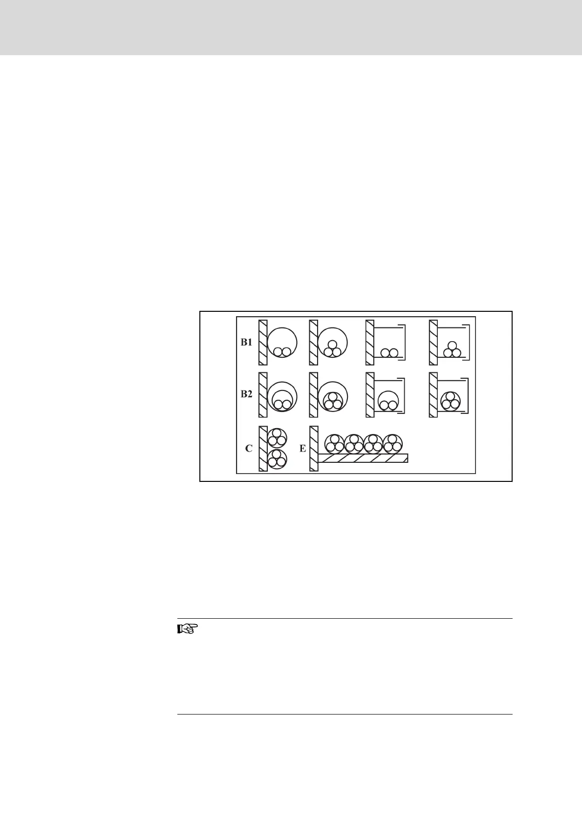
● B1 according to IEC 60364-5-52, e.g. stranded wires routed in ca‐
ble duct
● B2 according to IEC 60364-5-52, e.g. multi-core line routed in ca‐
ble duct
● E according to EN 60204-1, e.g. multi-core line routed on open ca‐
ble tray
● According to NFPA 79 (external wiring), UL 508A (internal wiring),
NEC, NFPA 70:
– 1 cable with 3 conductors, 1 neutral conductor and 1 equip‐
ment grounding conductor
– Routed in pipe on the wall
Internal wiring: Routing inside of control cabinet or of devices.
Field wiring: Routing of cross sections of terminal connectors wired
by the user (in the field).
B1 Conductors in installation pipes and in installation chan‐
nels that can be opened
B2 Cables or lines in installation pipes and in installation
channels that can be opened
C Cables or lines on walls
E Cables or lines on open cable trays
Fig. 5-11: Cable installation types (cf. IEC 60364-5-52; DIN VDE 0298-4;
EN 60204-1)
2. Recommendation for design of the fuses:
● International except for USA / Canada: Class gL-gG; 500 V, 690 V;
design NH, D (DIAZED) or D0 (NEOZED).
Characteristics
In the case of error (e.g. ground error at connections L+, L-),
fuses of characteristic gL (general-purpose fuse link for cables
and lines) and gG (general-purpose fuse link for general installa‐
tions) protect the lines in the frequency converter system.
To protect the semiconductors in the frequency converters, you
can use fuses of characteristic gR.
● USA / Canada: Class J; 600 V
Bosch Rexroth AG DOK-RCON02-FV*********-IB08-EN-P52/259
Rexroth Frequency Converter Fv
Installation