5.2.3 Control Circuit Wiring
● Terminal GND is the common terminal for analog signals, and SC is the
common terminal for switch values. Do not ground these terminals.
Shielded or twisted-pair cables should be used for wiring terminals for
the control circuit and must be separated from the wiring of main circuit
and high current circuits (including the control circuit of 200 V relay).
● 0.3...0.75 mm
2
cables are recommended for wiring of the control circuit.
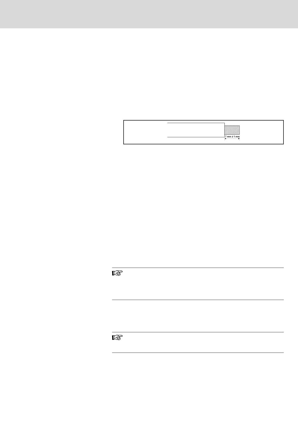
● Please strip the wire insulation for wiring of the control circuit, according
to the dimensions given below. Too long stripping may cause short cir‐
cuit of adjacent wires, and too short stripping may lead wires becoming
loose.
Fig. 5-10: Wire stripping length
● If a post terminal or single-conductor wire is used, use a cable with a di‐
ameter of less than 0.9 mm. If the cable is larger than 0.9 mm, the
screw may be stripped when being tightened up.
● Tighten up screws with typically 0.8 Nm / 7 lb-in torque after the cables
are inserted into the terminals.
● Cables may become disconnected and cause incorrect operation if not
tightened. However, over-tightening screws may break the component
to cause short circuit and incorrect operation.
5.2.4 Cable and Fuse Dimensions
Introduction
The power cable dimensions and the fuse dimensions are based on the VDE
0298 (part 4) and the standard for the European countries EN 60204-1.
The dimension for flexible wiring is according to VDE 0298 (part 4) and for fix
wiring according to VDE 0298 (part 4) or IEC 60364-5 (operating temperature
at the conductor 90 ℃).
The cable and fuse dimensions for USA / Canada are based on UL 508C.
The manufacturer of the machine / installation is responsible for
conformity with regional provisions and other standards that are
relevant for the respective application and the place of installa‐
tion. Also factors, such as installation methods, grounding, insula‐
tion and over-voltage protection must be taken into consideration.
National standards, such as NFPA in the USA, regional provisions, ground,
operating temperature, operating cycles, over-voltage protection and system
configuration can have a decisive impact on the dimensioning of the cables
and therefore they must be given priority over the above factors.
If, as a consequence of this, further requirement and cable de‐
signs arise that are not mentioned in this documentation, contact
your Bosch Rexroth sales partner.
DOK-RCON02-FV*********-IB08-EN-P Bosch Rexroth AG 49/259
Rexroth Frequency Converter Fv
Installation