5.3.4 NPN / PNP Jumper SW1
Fig. 5-19: NPN / PNP jumper SW1
The factory default setting of the jumper is NPN (Jumper contact
at 1−3, 4−6).
The jumper SW1 determines:
1. The internal 24 V power supply or an external 24 V power supply is
used for the inputs.
2. The inputs are activated by connection of 24 V to an input (PNP / active
input) or connection of 0 V to an input (NPN / passive input).
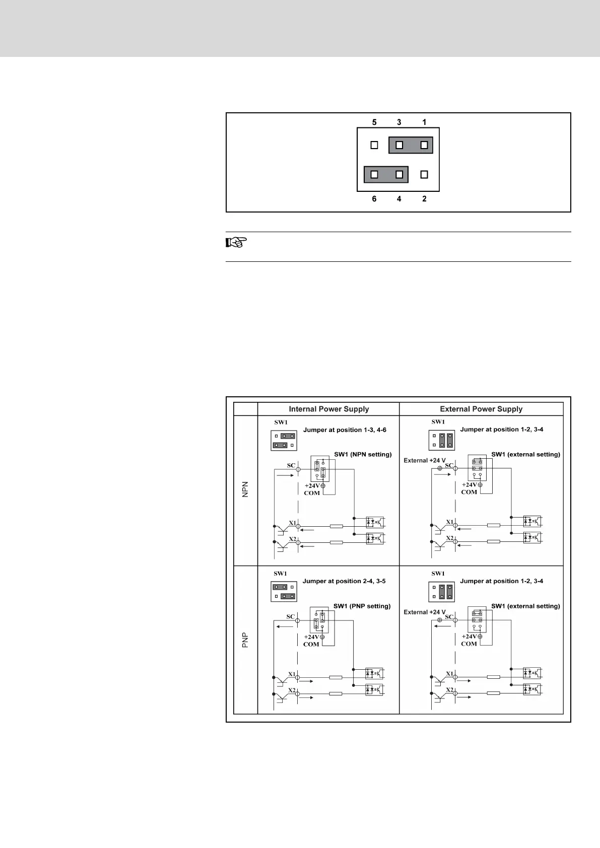
Modes and signal inputs
The jumper SW1 can switch between 0 V (NPN / passive input) and +24 V
(PNP / active input) inputs, respective external +24 V power supply is also
available, which improves the flexibility of signal input mode.
Fig. 5-20: NPN / PNP modes and signal inputs
DOK-RCON02-FV*********-IB08-EN-P Bosch Rexroth AG 59/259
Rexroth Frequency Converter Fv
Installation