Group E3: PID control
PID control is a common used process control approach suitable for flow con‐
trol, pressure control and temperature control.
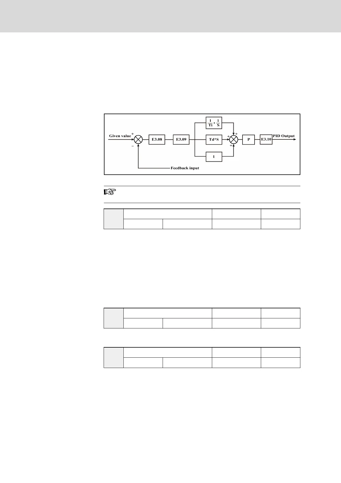
Based on proportional, integral and differential calculations of the difference
between the reference and the feedback, a negative feedback system can be
formed with the adjustment of the frequency converter output frequency to
limit the difference from the reference. The basic control principle is shown in
figure below.
Fig. 7-42: Process PID control
P represents the proportion gain, Ti represents the integral time
and Td represents the differential time.
E3.00
PID control mode Factory default 0
Setting range 0... 4 Minimum unit 1
● 0: PID control inactive
● 1: Analog input + analog feedback
● 2: Analog digital setting + analog feedback
● 3: Analog input + pulse encoder feedback
In this mode, parameter ‘Control mode’ b1.03 needs to be set as ‘0: V/F
control’.
● 4: Rotation speed digital setting + pulse encoder feedback
In this mode, parameter ‘Control mode’ b1.03 needs to be set as ‘0: V/F
control’.
E3.01
Analog digital setting Factory default 0.00
Setting range 0.00...10.00 V Minimum unit 0.01
Active when parameter ‘PID control mode’ E3.00 is set to ‘2: Analog digital
setting + analog feedback’.
E3.02
Rotation speed digital setting Factory default 0
Setting range 0...24,000 rpm Minimum unit 1
● Active when parameter ‘PID control mode’ E3.00 is set to ‘4: Rotation
speed digital setting + pulse encoder feedback’.
● In closed loop PID control, configuration of reference, feedback and
control mode is shown in table below.
Bosch Rexroth AG DOK-RCON02-FV*********-IB08-EN-P150/259
Rexroth Frequency Converter Fv
Parameter Settings