Transmission
The transmission is of RTU (remote terminal unit) mode with frames contain‐
ing no message header or end mark. A typical RTU frame format is shown in
table below.
Slave address
(1 byte)
Modbus function code
(1 byte)
Data
(Multiple bytes)
CRC16 check information
(2 bytes)
Tab. 12-1: Typical RTU frame format
Data are transmitted in binary codes.
If an interval is 3.5 characters or longer, it is taken as the end of the frame.
Therefore, all information in a frame must be transmitted in a continuous data
flow. If an interval of 3.5 characters or longer occurs before a complete frame
is sent out, the receiving device will consider the information has ended and
start processing it, and mistake following bytes for a new frame’s address.
Similarly, if the interval between a new frame and the previous one is less
than 3.5 characters, the receiving device will consider it as a part of the previ‐
ous frame. Due to confusion of the frames, the CRC check will fail and lead
to a communication fault.
Data format and sending sequence of one byte:
● 1 start bit, 8 data bits
● 1 parity check bit or no parity check bit
● 1 or 2 stop bits
CRC (Cyclic redundancy check):
● CRC16, lower bytes first and higher bytes later
Slave address:
● The address of a frequency converter may be any between 1 and 247.
● The address 0 is reserved for broadcasting. Frequency converters will
act upon the request but make no acknowledgment.
● Each address must be unique in the network.
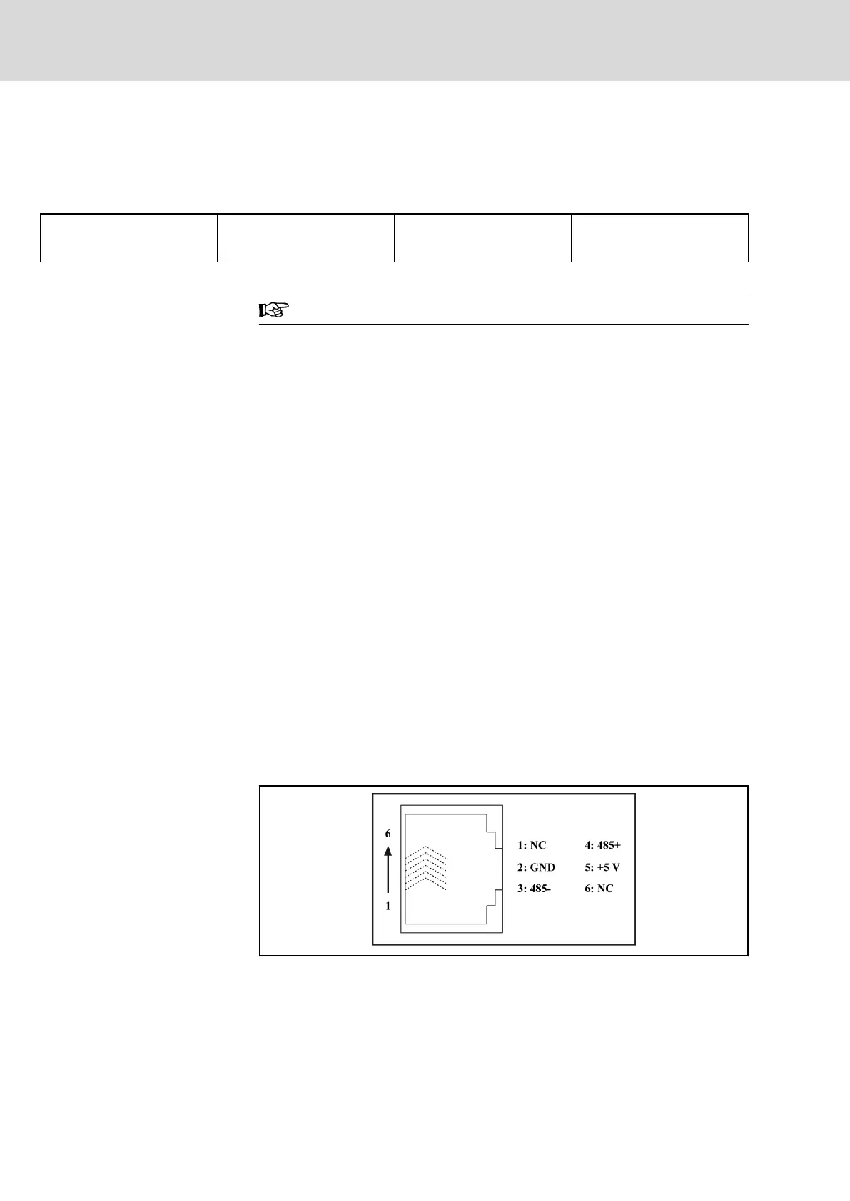
12.2.2 Interface
The RJ11 communication interface of Fv is shown in figure below.
Fig. 12-1: Fv RJ11 communication interface
Bosch Rexroth AG DOK-RCON02-FV*********-IB08-EN-P218/259
Rexroth Frequency Converter Fv
Communication Protocols