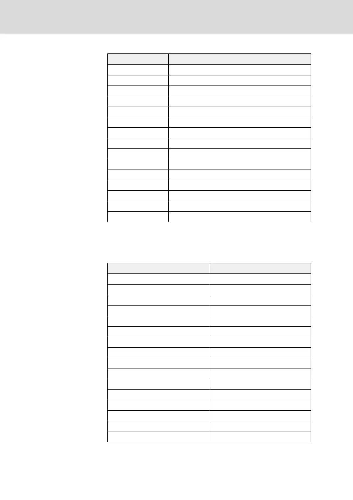
No. Fault code name
12 Communication fault (R.S.)
13 Circuit disconnection (C.F.)
14 Encoder speed detection fault (PULS)
15 Motor overheat (M.O.H.)
16 EMI (CPU-)
17 Short circuit (S.C.)
18 Reserved
19 L1, L2, L3 phase failure (IPH.L)
20 U, V, W phase failure (OPH.L)
21 Frequency converter overheat (C.O.H.)
22 Parameter setting fault (PRSE)
23 Parameter auto-tuning fault (TUNE)
24 Frequency converter over load pre-warning 2 (O.L.-3)
25 Broken wire alarm (B.W.A)
26 Broken wire fault (B.W.F)
Tab. 12-17: Fault codes and meanings_Modbus
Communication monitor registers (0x5001...0x5013)
Communication monitor registers are read-only. The relationship between the
register addresses and monitored values are shown in table below.
Register address Monitored value
0x5001 Output frequency
0x5002 Reference frequency
0x5003 Output current
0x5004 DC bus voltage
0x5005 Heat sink temperature
0x5006 Output voltage
0x5007 Output power
0x5008 Torque current
0x5009 Exciting current
0x500A Output speed
0x500B Reference speed
0x500C User-defined reference value
0x500D User-defined output value
0x500E Reference torque
0x500F Digital inputs status
0x5010 Encoder speed feedback
Bosch Rexroth AG DOK-RCON02-FV*********-IB08-EN-P228/259
Rexroth Frequency Converter Fv
Communication Protocols

 Loading...


