Home
REXROTH
DC Drives
Fv Series
Page 18 (Operating Panel Cable Type Coding)
REXROTH Fv Series - Operating Panel Cable Type Coding; Brake Resistor Type Coding
262 pages
Manual
Save Page as PDF
To Next Page
To Next Page
To Previous Page
To Previous Page
Loading...
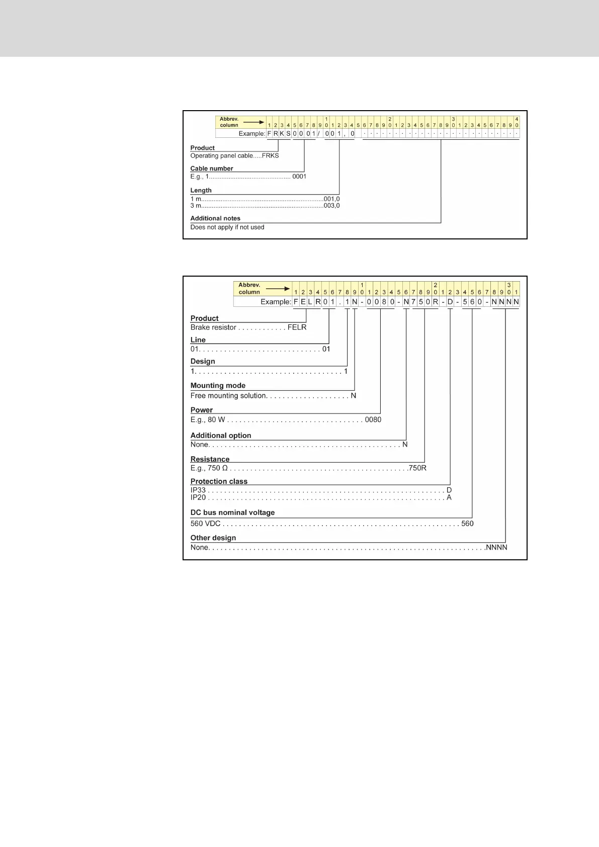
Operating panel cable type coding
Fig. 1-7:
Operating panel cable type coding
Brake resistor type coding
Fig. 1-8:
Brake resistor type coding
Bosch Rexroth AG
DOK-RCON02-FV*********-IB08-EN-P
16/
259
Rexroth Frequency Converter Fv
Introduction
17
19
Table of Contents
Main Page
Default Chapter
5
Table of Contents
5
1 Introduction
13
Introduction to the Documentation
13
Definition
14
Type Coding
15
Type Coding of Fv
15
Type Coding of Fv Function Modules
16
Engineering Software Type Coding
16
Type Coding of Fv Accessories
16
PROFIBUS Adapter Type Coding
16
Encoder Adapter Type Coding
17
Remote Operation Adapter
17
Interface Adapter Cable Type Coding
17
Operating Panel Cable Type Coding
18
Brake Resistor Type Coding
18
External Brake Chopper Type Coding
19
EMC Filter Type Coding
19
Delivery and Storage
20
Brief Introduction
20
Scope of Supply
20
Transport of the Components
21
Storage of the Components
21
Fv Description
22
Certification
22
CE Certification
22
UL Certification
23
Rcm
24
Properties of the Basic Device Fv
25
Interfaces
25
Cooling Types
25
Version Matching Table
26
2 Safety Instructions for Electric Drives and Controls
27
Definitions of Terms
27
Explanation of Signal Words and the Safety Alert Symbol
28
General Information
28
Using the Safety Instructions and Passing Them on to Others
28
Requirements for Safe Use
29
Hazards by Improper Use
30
Instructions with Regard to Specific Dangers
30
Protection against Contact with Electrical Parts and Housings
30
Protective Extra-Low Voltage as Protection against Electric Shock
31
Protection against Dangerous Movements
32
Protection against Magnetic and Electromagnetic Fields During Operation and Mounting
33
Protection against Contact with Hot Parts
33
Protection During Handling and Mounting
34
3 Important Directions for Use
35
Appropriate Use
35
Inappropriate Use
35
4 Fv Mounting
37
Mounting
37
Fv Dimensions and Figure
39
Fv Dimensions
39
Fv Figure
40
5 Installation
43
Fv Disassembly and Assembly
43
Removal and Mounting of Operating Panel
43
Removal of Operating Panel
43
Mounting of Operating Panel
43
Removal and Mounting of Adapter
44
Removal of Adapter
44
Mounting of Adapter
44
Drive System Wiring
45
Block Diagram
45
Main Circuit Wiring
46
Main Circuit Wiring Cautions
46
Main Circuit Wiring Diagram
47
Main Circuit Wiring Steps
48
Control Circuit Wiring
51
Cable and Fuse Dimensions
51
Introduction
51
Recommendation on Cable Dimensioning
52
Dimensioning Variables of the Table Values
54
Wiring Dimensions for Terminals
55
Wiring Terminals Description
56
Main Circuit Terminals
56
Main Circuit Terminals Description
56
Main Circuit Terminals Illustration
56
Control Circuit Terminals
57
Control Circuit Terminals Description
57
Control Circuit Terminals Illustration
59
Analog Input Terminals (±10 V, VR1, VR2, VR3, GND, +I)
60
Jumper Wiring
60
NPN / PNP Jumper SW1
61
Encoder Signal Selection
62
6 Commissioning
65
Operating Panel
65
Overview
65
3-Level Menu Structure
66
Operation Mode Description
67
Example of Operating Panel Operation
67
Commission Process
68
Check and Preparation before Commissioning
68
Notes on Commissioning
69
Fv Basic Parameter Fast Setting
69
Example: Commissioning of Frequency Converter with Potentiometer
70
Restore Parameters to Factory Defaults
70
Solutions for Simple Fault During Commissioning
71
Notes on Frequent Start and Stop
71
7 Parameter Settings
73
Main Functions
73
Control Command
73
Frequency Setting
74
Start Control
75
Stop Control
76
Linear / S-Curve Acceleration / Deceleration
77
Logic Control
78
PID Control
79
Frequency Setting Via Analog and Pulse Inputs
80
Multiple Function Digital Inputs
81
Analog Outputs
82
Digital Outputs
83
Description of Attribute Symbols in Parameter Tables
84
Parameters Functions
85
Category B: Basic Parameters
85
Group B0: System Parameters
85
Group B1: Basic Parameters
86
Category S: Standard Parameters
88
Group S0: V/F Control
88
Group S1: Vector Control
88
Group S2: Motor and Encoder Parameters
89
Group S3: Control Parameters
90
Category E - Extended Parameters
91
Group E0: Analog and Digital Inputs
91
Group E1: Digital and Analog Outputs
93
Group E2: Multi-Speed and Logic Control
95
Group E3: PID Control
98
Group E4: Protection and Fault Parameters
99
Group E5: Extended Parameters
101
Category H: Advanced Parameters
102
Group H0: Communication Parameters
102
Notes on Function Groups
103
Category B: Basic Parameters
103
Group B0: System Parameters
103
Group B1: Basic Parameters
107
Category S: Standard Parameters
116
Group S0: V/F Control
116
Group S1: Vector Control
120
Group S2: Motor and Encoder Parameters
123
Group S3: Control Parameters
125
Category E: Extended Parameters
130
Group E0: Analog and Digital Inputs
130
Group E1: Analog and Digital Outputs
141
Group E2: Multi-Speed and Logic Control
146
Group E3: PID Control
152
Group E4: Protection Parameters
156
Group E5: Extended Parameters
162
Category H: Advanced Parameters
164
Group H0: Communication Parameters
164
8 Fault Types and Solutions
167
9 Technical Data
171
Electrical Data
171
General Technical Data
172
Derating of Electrical Data
174
Derating and Ambient Temperature
174
Derating and Mains Voltage
175
Derating of the Output Current Depending on the Pulse Frequency
176
Electromagnetic Compatibility (EMC)
177
EMC Requirements
177
General Information
177
Noise Immunity in the Drive System
177
Noise Emission of the Drive System
179
Ensuring the EMC Requirements
182
EMC Measures for Design and Installation
183
Rules for Design of Installations with Drive Controllers in Compliance with EMC
183
EMC-Optimal Installation in Facility and Control Cabinet
185
Control Cabinet Mounting According to Interference Areas - Exemplary Arrangements
186
Design and Installation in Area a - Interference-Free Area of Control Cabinet
187
Design and Installation in Area B - Interference -Susceptible Area of Control Cabinet
189
Design and Installation in Area C - Strongly Interference-Susceptible Area of Control Cabinet
189
Ground Connections
190
Installing Signal Lines and Signal Cables
191
General Measures of Radio Interference Suppression for Relays, Contactors, Switches, Chokes and Inductive Loads
192
10 Accessories
193
EMC Filter
193
The Function of EMC Filter
193
External EMC Filter Type
193
Technical Data
194
Mechanical Data
194
Electrical Data
197
Brake Components
198
Brake Chopper
198
The Function of Brake Chopper
198
Internal Brake Chopper
198
External Brake Chopper (18K5 and above Models)
199
Brake Resistor
203
Brief Introduction
203
Brake Resistor Selection
204
Brake Resistor in Aluminum Housing
207
Brake Resistor Box
209
Encoder Adapter
211
The Function of Encoder Adapter
211
Encoder Adapter Dimensions
211
Encoder Adapter Terminals
212
PROFIBUS Adapter
213
Accessories for Control Cabinet Mounting
213
Remote Operation
213
Operating Panel Cable for Control Cabinet Mounting
214
Engineering Software
214
11 Additional Information
215
Simple Applications of Process Control
215
Automatic Constant Pressure Water Control System
215
Closed-Loop Speed Control System
215
Discharging of Capacitors
216
Discharging of DC Bus Capacitors
216
Discharging Device
216
Operating Principle
216
Dimensioning
216
Installation
217
Activation
217
12 Communication Protocols
219
Introduction
219
Modbus Protocol
219
Protocol Descriptions
219
Transmission
220
Interface
220
Protocol Functions
221
Supported Functions
221
Function Descriptions
222
Communication Mapping Register Address Distribution
227
Introduction
227
Frequency Converter Parameter Registers
227
Communication Control Registers (0X4000, 0X4001, 0X4002)
228
Communication State Feedback Register (0X5000)
229
Communication Monitor Registers (0X5001
230
Modbus Communication Example
231
Special Notes
233
Communication Networking
234
Networking
234
Recommendations on Networking
234
PROFIBUS Protocol
235
Protocol Description
235
PROFIBUS-Adapter
235
Technical Data
235
Functions
235
Network Structure
236
Electrical Installations
236
Outline Structure
236
Adapter Terminal Configuration
236
Requirements for PROFIBUS Link
237
Relationship between Communication Rate and Cables
237
EMC Measures
238
Periodical Data Communication
238
PPO Data Type
238
PKW Parameter Area
239
PZD Process Data Area
243
Addressing of Communications Function Code Parameter Group and Index Number Within the Group
248
Communication Parameter Configuration
249
Communication Related Parameter Settings in Fv
249
Parameter Configuration of Master
249
GSD File
249
Faults and Analysis
250
LED Display Analysis
250
Diagnosis Information of Master
250
13 Service and Support
253
14 Environmental Protection and Disposal
255
Environmental Protection
255
Disposal
255
Index
257
Other manuals for REXROTH Fv Series
Quick Start Guide
44 pages
Related product manuals
REXROTH EFC 3610 Series
422 pages
REXROTH IndraDrive
312 pages
REXROTH IndraDrive C
306 pages
DOK-DIAX04-ELS-06VRS**-WA01-EN-P Series
114 pages
REXROTH EFC5610
16 pages
REXROTH RD 500 Series
276 pages
REXROTH EFC 5610 Series
422 pages
REXROTH DIAX04
114 pages