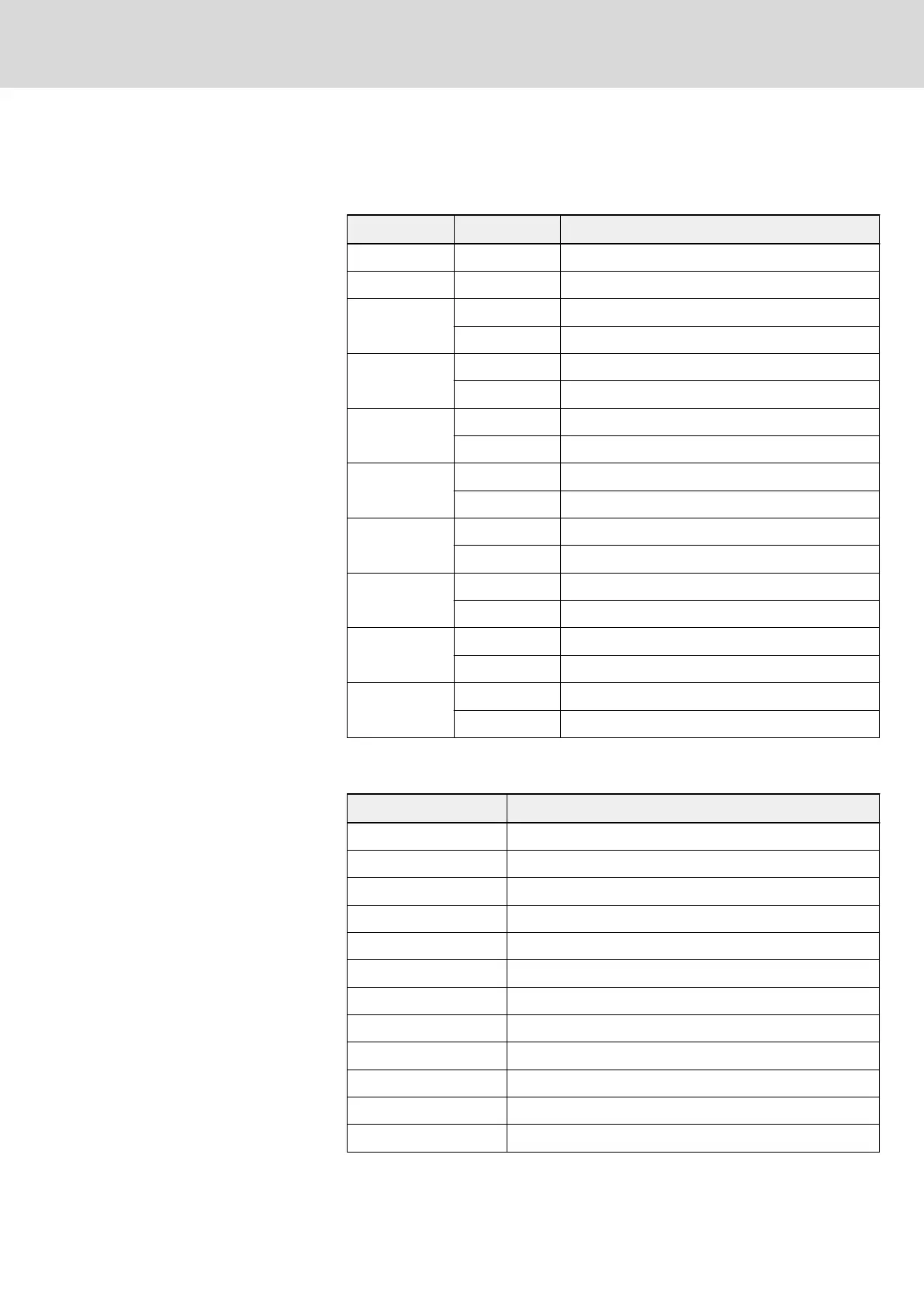
Communication state feedback register (0x5000)
The frequency converter state can be monitored by reading the register. This
register is read-only. The definition of each bit is shown in table below.
bit Value Description
15...11 – Fault code
10...8 – Reserved
7
1 Fault
0 No fault
6
1 Stall over current
0 Normal
5
1 Stall over voltage
0 Normal
4
1 Decelerating
0 Not in deceleration
3
1 Accelerating
0 Not in acceleration
2
1 Jogging
0 Not in jog
1
1 In run
0 In stop
0
1 Reverse
0 Forward
Tab. 12-16: Communication state word register (0x5000)_bit definition
The meanings of fault codes are described in table below.
No. Fault code name
0 No fault record
1 Over current at constant speed (O.C.-1)
2 Over current in acceleration (O.C.-2)
3 Over current in deceleration (O.C.-3)
4 Over voltage at constant speed (O.E.-1)
5 Over voltage in acceleration (O.E.-2)
6 Over voltage in deceleration (O.E.-3)
7 Frequency converter overload (O.L.-1)
8 Motor overload (O.L.-2)
9 CPU read/write fault(R.E.)
10 Operating panel read/write fault (KEY-)
11 External fault (E.-St)
DOK-RCON02-FV*********-IB08-EN-P Bosch Rexroth AG 227/259
Rexroth Frequency Converter Fv
Communication Protocols