PID
control mode
Reference Feedback
Frequency converter
control mode
[E3.00]=1 External analog input
External analog
signal feedback
[b1.03]=0, 1, 2
0 or 1 in most cases
[E3.00]=2
Analog digital setting
E3.01
External analog
signal feedback
[E3.00]=3 External analog input
Pulse encoder
feedback
[b1.03]=0
(V/F control)
[E3.00]=4
Rotation speed digital
setting E3.02
Pulse encoder
feedback
Tab. 7-18: Configuration in closed loop PID control
E3.03
Analog feedback channel Factory default 0
Setting range 0...3 Minimum unit 1
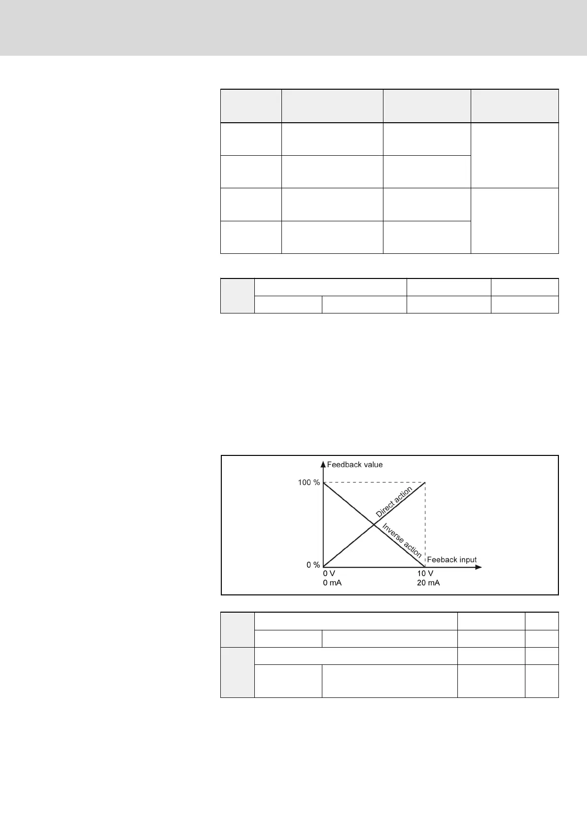
Used to select analog feedback channel when [E3.00] = 1 or 2:
● 0: +I direct action is the feedback in the PID control
● 1: +I inverse action is the feedback in the PID control
● 2: VR1 direct action is the feedback in the PID control
● 3: VR1 inverse action is the feedback in the PID control
● 4: VR2 direct action is the feedback in the PID control
● 5: VR2 inverse action is the feedback in the PID control
● 6: VR3 direct action is the feedback in the PID control
● 7: VR3 inverse action is the feedback in the PID control
Fig. 7-43: Feedback modes
E3.04
P: Proportional gain Factory default 1.500
Setting range 0.000...10.000 Minimum unit 0.001
E3.05
Ti: Integral time Factory default 0.00
Setting range
0....00...100.00 s
(0.00 represents no integral)
Minimum unit 0.01
DOK-RCON02-FV*********-IB08-EN-P Bosch Rexroth AG 151/259
Rexroth Frequency Converter Fv
Parameter Settings