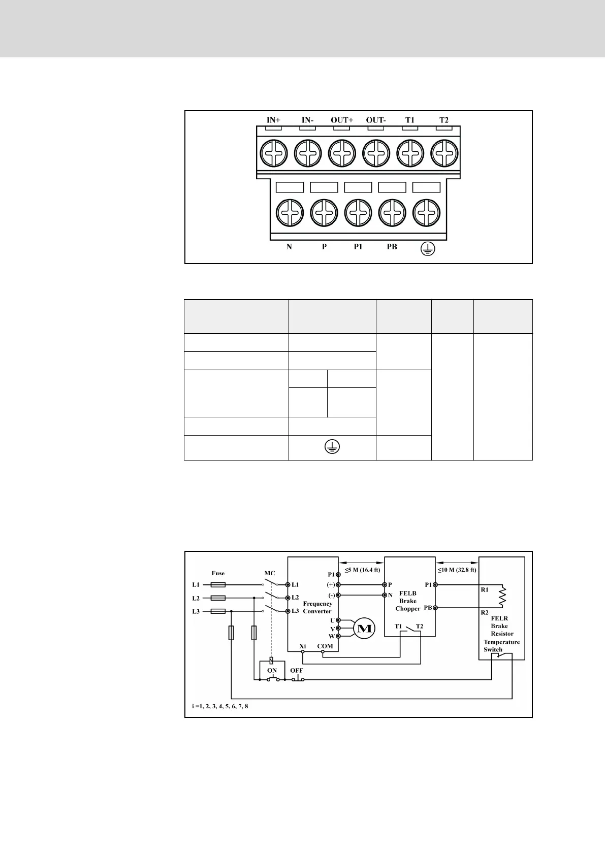
Brake chopper terminals
Fig. 10-9: Brake chopper terminals
Wiring on each terminal of brake choppers
Name of
terminal
Sign of
terminal
Cable size
[AWG]
Screw
size
Torque
Input power supply N, P
10...12
M4
18 kgf–cm
(15.6 in–ibf)
Brake resistor P1, PB
Multiple units in parallel
input IN+, IN-
18...20output
OUT+,
OUT-
Fault output T1, T2
Grounding 10...12
Tab. 10-6: Wiring on each terminal of brake choppers
Basic wiring diagram
To avoid brake chopper damage or break down in case of overload or fault
conditions, please refer to the following wiring diagram. The brake chopper
FELB fault switch should be connected to Xi of Fv. The temperature switch of
the brake resistor should be in series with the line contactor coil circuit.
Fig. 10-10: Basic wiring diagram
Bosch Rexroth AG DOK-RCON02-FV*********-IB08-EN-P198/259
Rexroth Frequency Converter Fv
Accessories