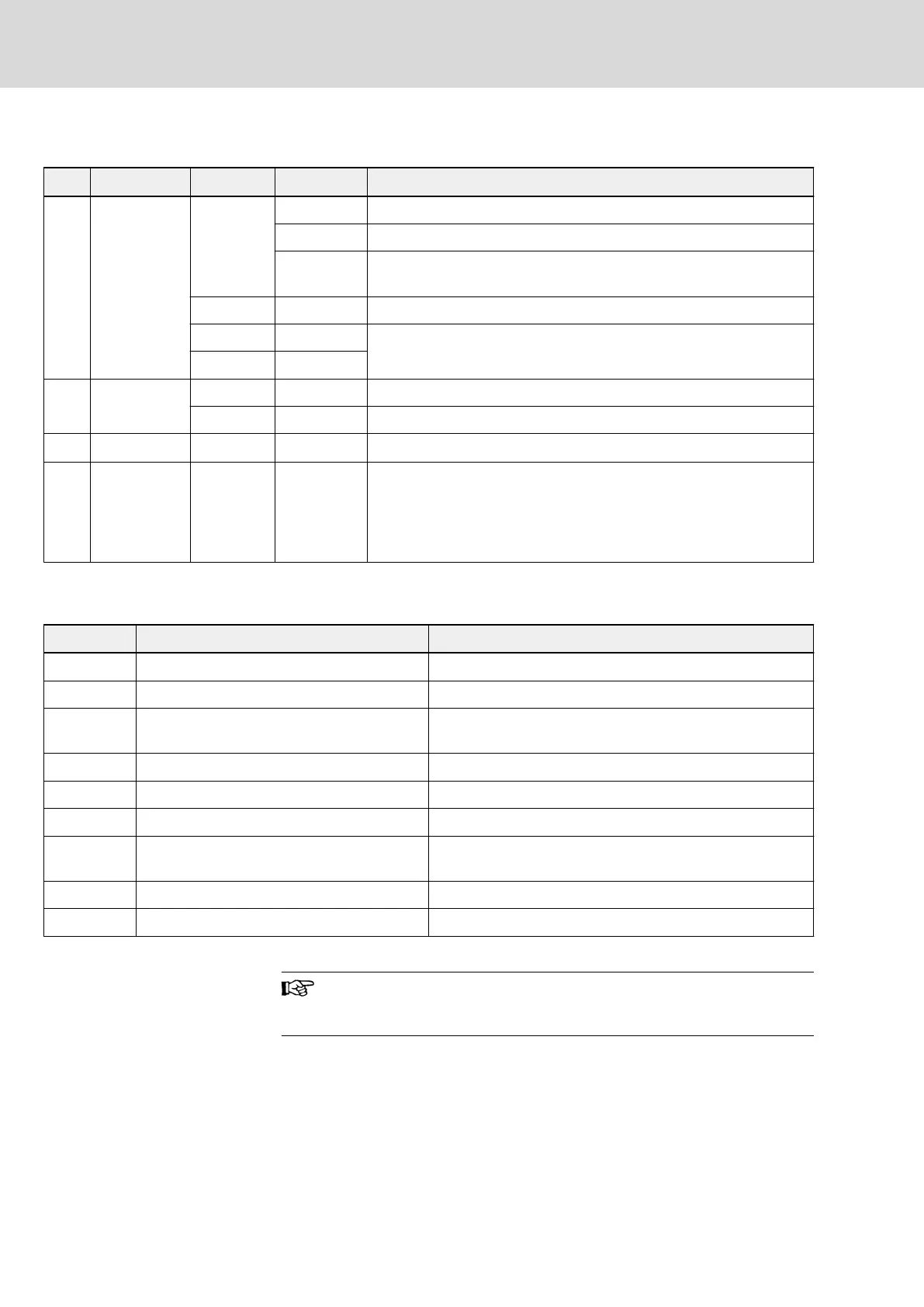
● Response data frame in PKW area
Word Identifier bit Value Description
1
st
ID
15...12
0000B No task
0001B Correct in reading or modifying function code parameter
0111B
Wrong in reading or modifying function code parameter, and fault
message is show in VALUE_low
11 0 Reserved, default is 0
10...8 000B
Group No. of function code parameter
7...0 xxH
2
nd
IND
15...8 xxH Index serial number of function code parameter within the group
7...0 0 Reserved, default is 0
3
rd
VALUE_high 15...0 0 Reserved, default is 0
4
th
VALUE_low 15...0 xxxxH
1. When reading parameters, it returns to read parameter value.
2. when modifying parameters, it is modified value.
3. It returns 0 in case of no operation.
4. It returns fault code when PKW area execution fails.
Tab. 12-26: Response data frame in PKW area_from slave to master
● Fault message after execution failure in PKW area
Fault code Meaning Reason
1 Password locked User password is locked
2 Invalid command codes in PKW area Command codes (bit15...12 of ID) are not 0, 1 or 2.
3 Invalid parameter addresses in PKW area
Invalid function group or index number of the function group,
or insufficient access/rights
4 Invalid parameter value in PKW area Data to write out of range
5 In running, can not be modified Frequency converter is running
6 Read-only parameters Parameter are read-only, can not be written
7 Invalid operation
Function code does not support write or multiple write via
external computer
8 Communication data fault in PKW Conductor interference
9 EEPROM read/write fault EEPROM write operation is not complete
Tab. 12-27: PKW area fault codes
Communication line which is subject to hardware disconnection
fault will also lead to execution failure in PKW area. The fault
code will be given in status word of PZD area.
● Example of parameter operation in PKW area
In real application, the PROFIBUS adapter communicates with the master
through messages in PPO structure. Among the 5 PPOs stated in fig. 12-6
"PPO type" on page 236, PPO 1, PPO 2 and PPO5 apply both PKW area
and PZD area. In following examples, PKW area data frames are taken from
complete PPO message to describe its request and response data frames.
Bosch Rexroth AG DOK-RCON02-FV*********-IB08-EN-P238/259
Rexroth Frequency Converter Fv
Communication Protocols

 Loading...


