4.20
SEL-787 Relay Instruction Manual Date Code 20081022
Protection and Logic Functions
Basic Protection
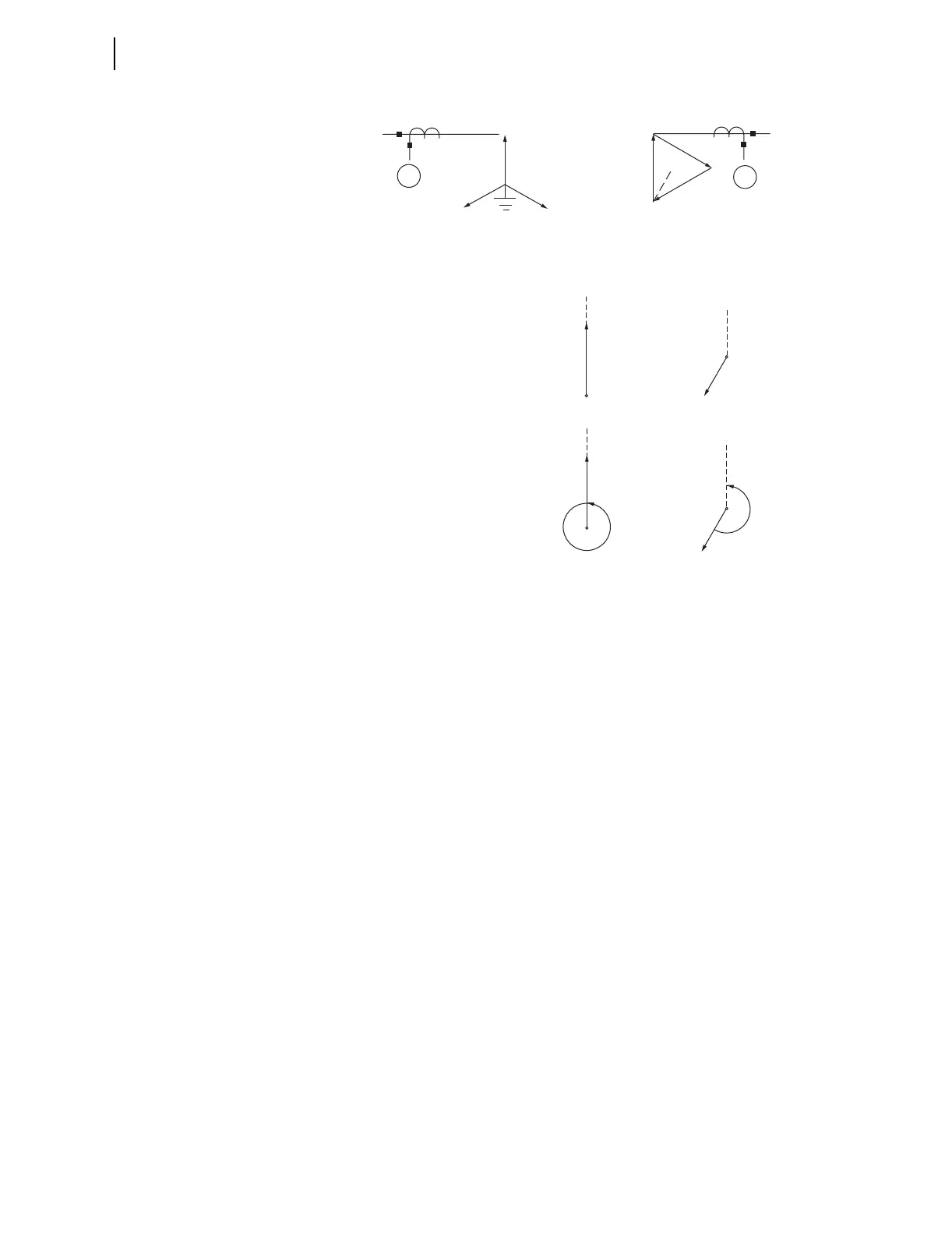
Figure 4.9 Example 2 for WnCTC Selection
1. Establish the phase direction for the three A line terminals.
Figure 4.9 shows these phase directions in the first line below
the transformer drawing. Based on the transformer designation,
the terminal directions are shown at “noon,” “7 o'clock,” and “4
o'clock.”
2. Adjust the transformer winding directions based on the CT
connections. Neither windings need correction, because they
both have wye-connected CTs.
3. Select a reference direction. In this example we have chosen the
primary winding position at “noon.”
4. Select values of WnCTC for each winding. For the sake of later
discussion, we have selected W1CTC = 0 as the setting for
Winding 1, the reference winding. Beginning at the Winding 2
direction at “7 o'clock,” adjust the Winding 2 position in the
CCW direction until arrival at the “noon” reference direction.
This procedure requires seven 30-degree increments, or seven
“hours” of adjustment. Thus, we choose W2CTC = 7 as the
setting.
5. Ensure that there will be no wye windings with wye CTs and a
setting of WnCTC = 0. In this case the primary winding is wye-
connected and has wye-connected CTs. In step 4 we set
W1CTC at zero because Winding 1 was the reference winding.
However, this setting violates the condition that WnCTC not
equal 0. Instead of a zero shift, we must shift Winding 1 360
degrees by setting W1CTC = 12. This solves the zero-sequence
Y
1
115 kV
A
B
C
34.5 kV
2
B
C
A
Y
(DAB)
Yd7 Connection (ABC Rotation)
A
A
(REF.)
W2CTC
A
W1CTC
Xfmr
Phase
Xfmr + CT
Phase
CTComp: W1CTC = 12
(remove I
0
)
W2CTC = 7
Terminal A