Section 02 ENGINE
Subsection 07 (PTO HOUSING AND MAGNETO)
1
R1503motr53A
2
3
1
TYPICAL
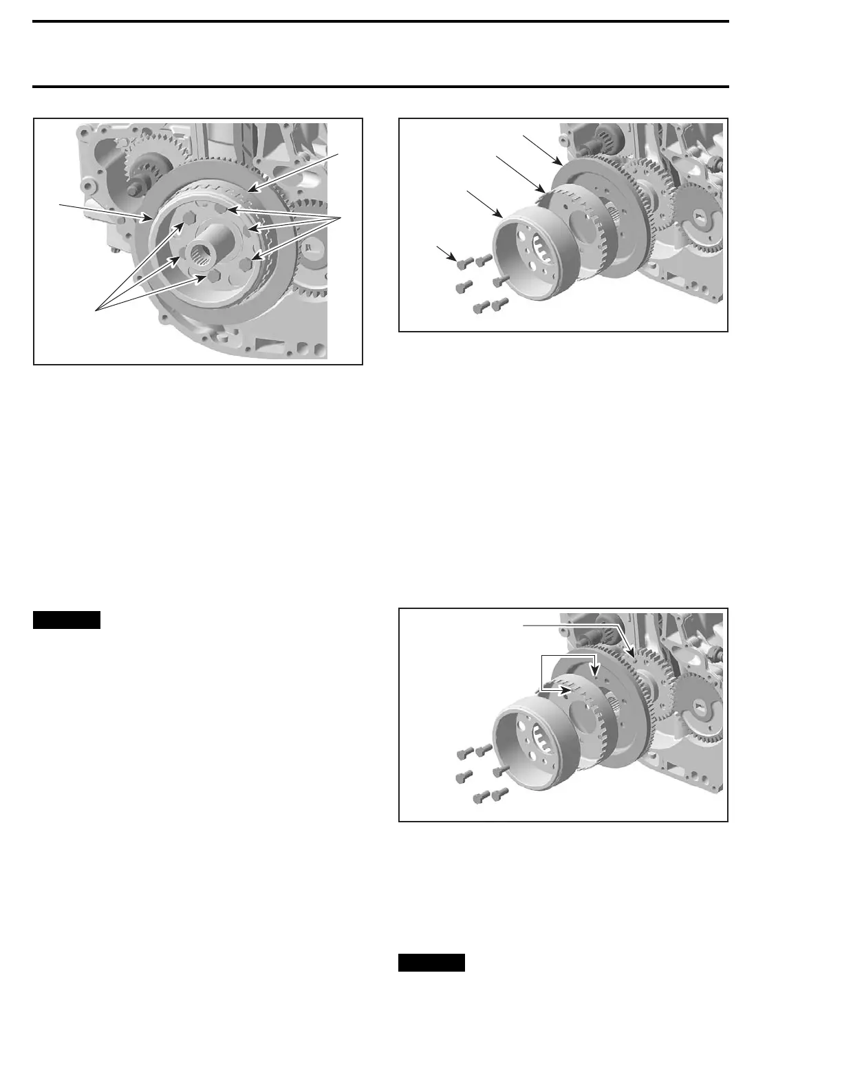
1. Rotor retaining screws
2. Rotor
3. Trigger wheel
Rotor and Trigger Wheel Installation
For installation, reverse the removal procedure.
However, pay attention to the following.
Align the trigger wheel to the crankshaft using the
location pin on the crankshaft end.
Install NEW OEM rotor screws and torque them
to 15 N•m (133 lbf•in) using a crisscross pattern.
Finish tightening screws with an additional 50° ro-
tation with a torque angle gauge.
NOTICE
Always install NEW OEM screws
with pre-applied threadlocker. These are
stretch screws that are one time use only.
Not replacing rotor screws may lead to engine
damage and failure.
RING GEAR
Ring Gear Removal
Lock crankshaft. Refer to
CYLINDER BLOCK
sub-
section for procedure.
Remove the PTO housing cover, see procedure in
this subsection.
Remove and discard the magneto rotor retaining
screws.
Pull rotor and trigger wheel off crankshaft end.
Pull rotor, trigger wheel, and ring gear off crank-
shaft end.
1
R1503motr54A
2
3
4
TYPICAL
1. Magneto rotor retaining screws
2. Rotor
3. Trigger wheel
4. Ring gear
Ring Gear Inspection
Inspect ring gear for damages. Pay particular at-
tention to teeth condition. If badly worn, cracked,
or broken teeth are found, replace ring gear.
Ring Gear Installation
For installation, reverse the removal procedure.
However, pay attention to the following.
Align the ring gear and trigger wheel to the crank-
shaft using the location pin on the crankshaft end.
1
R1503motr54B
2
TYPICA
L
1. Location pin
2. Location pin holes
Instal
l NEW OEM rotor screws and torque them
to 15 N
•m (133 lbf•in) in a crisscross pattern.
Finish tightening screws with an additional 50° ro-
tation with a torque angle gauge.
NOTICE
Alway
s install NEW OEM screws
with p
re-applied threadlocker. These are
stret
ch screws that are one time use only.
Not re
placing rotor screws may lead to engine
damag
e and failure.
82 smr2009-022

 Loading...

