Section 02 ENGINE
Subsection 09 (COOLING SYSTEM)
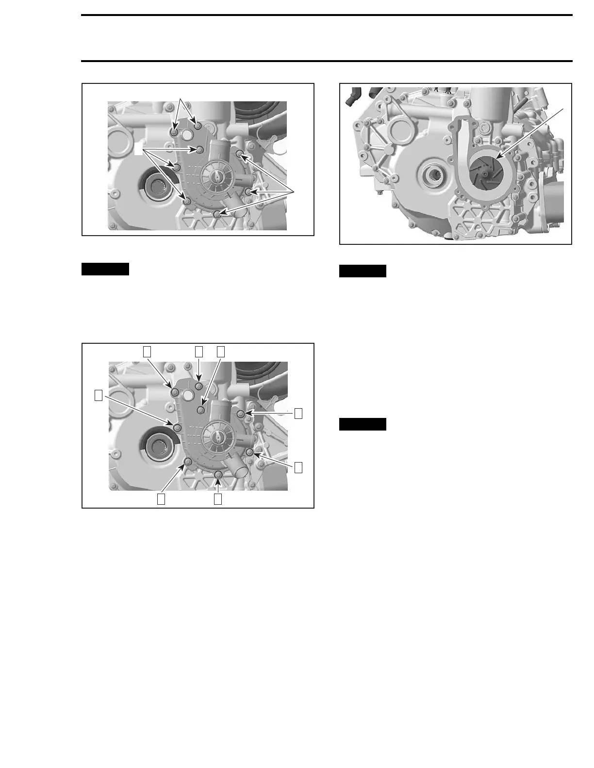
F18E10A
2
1
1
1. Screws M6 x 25
2. Screws M6 x 105
NOTICE
To prevent leaking, take care that the
gaskets are exactly in groove when you rein-
stall the water pump housing.
Tighten screws to 9 N•m (80 lbf•in) using the fol-
lowing sequence.
F18E10B
32
4
5
1887
6
WATER
PUMP IMPELLER
Water Pump Impeller Removal
Remov
ethe
WATER PUMP HOUSING
, see pro-
cedur
e in this subsection.
Unscrew the impeller clockwise.
1
F18E13A
1. Impeller
NOTICE
Coolant/oil pump shaft and impeller
have left-hand threads. Remove by turning
clockwise and install by turning counterclock-
wise.
WaterPumpImpellerInspection
Check impeller for cracks or other damage. Re-
place impeller if damaged.
Water Pump Impeller Installation
The installation is the opposite of the removal pro-
cedure. Pay attention to the following details.
NOTICE
Be careful not to damage impeller
wings during installation.
Torque impeller to 3 N•m (27 lbf•in).
THERMOSTAT
The thermostat is a single action type.
Thermostat Removal
Remove the
WATER PUMP HOUSING
, see pro-
cedure in this subsection.
NOTE: The thermostat is located inside the water
pump housing.
Thermostat Test
To check the operation of the thermostat, put it in
water and heat water.
Look inside the cylinder head return hose con-
nection to see the movement of the thermostat.
Thermostat should open when water tempera-
ture reaches 87°C (189°F).
If there is no operation, replace the water pump
housing.
smr2009-024 123

 Loading...

