Section 06 STEERING AND PROPULSION
Subsection 01 (STEERING AND O.T.A.S.)
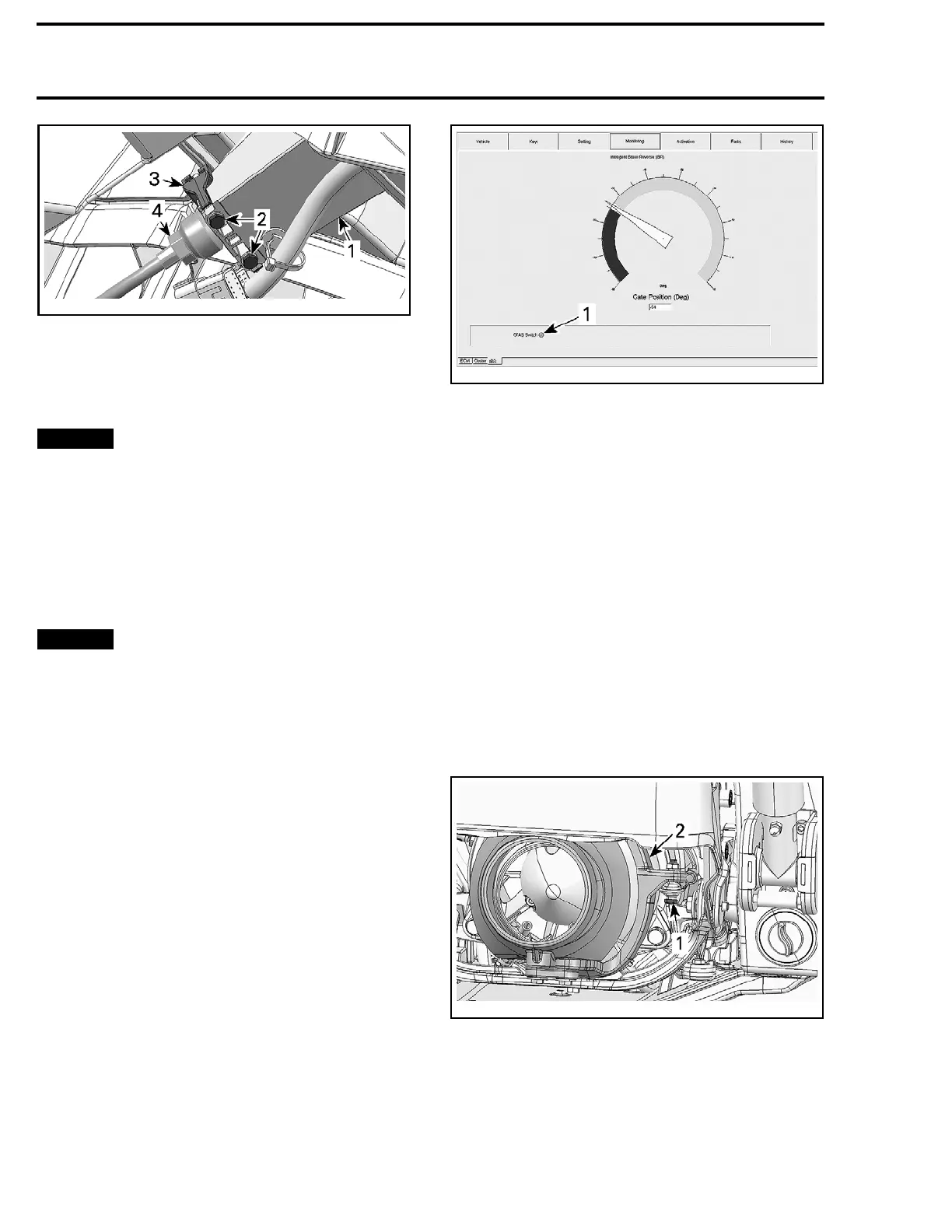
smr2009-042-007_a
1. Steering column
2. Steering column clamp bolts
3. Steering column clamp
4. Steering cable adjusting nut
After adjustment, torque steering column clamp
bolts to 6 N•m (53 lbf•in).
NOTICE
Verify when the handlebar is turned
completely to the left or right side, that there is
no interference with jet pump or reverse parts.
INSPECTION
O.T.A.S. OPERATION
This test is to be performed with the watercraft in
the water (test tank or on a trailer).
NOTICE
If the test is performed on a trailer,
ensure no debris or rocks can damage the jet
pump.
Connect B.U.D.S.Refer to
COMMUNICATION
TOOLS AND B.U.D.S. SOFTWARE
subsection.
Start engine.
Raise engine speed higher than 4000 RPM for
more than 1 second.
Release throttle while steering is in the straight
ahead position.
Within 1 to 3 seconds, turn handlebar all the way
to one side.
The O.T.A.S. should come on by keeping or
increasing engine speed to approximately
3000 RPM.
Immediately look in B.U.D.S. to see if the O.T.A.S.
system “LED” turns on.
smr2009-037-034_a
MONITORING AND IBR TABS
1. O.T.A.S. "LED"
Then, engine speed will gradually decrease to idle
speed within approximately 5 seconds.
Repeat test for the other side.
If O.T.A.S. system “LED” does not turn on, check
for fault codes.
If the RPM does not behave as described, check
the O.T.A.S. switch.
PROCEDURES
NOZZLE
Nozzle Removal
Raise the iBR gate by activating the iBR override
function. Refer to
IBR AND VTS
subsection.
Disconnect steering cable from nozzle arm.
smr2009
-037-004_a
1. Steering cable bolt
2. Nozzle arm
From th
e top and underneath nozzle, remove
hexago
nal screws retaining nozzle link rod to noz-
zle arm
and socket screws securing the nozzle to
the VTS
trim ring.
362 smr2009-037

 Loading...

