Section 04 FUEL SYSTEM
Subsection 02 (ELECTRONIC FUEL INJECTION (EFI))
Trigger Wheel Inspection
Refer to
PTO HOUSING AND MAGNETO
in the
ENGINE
section.
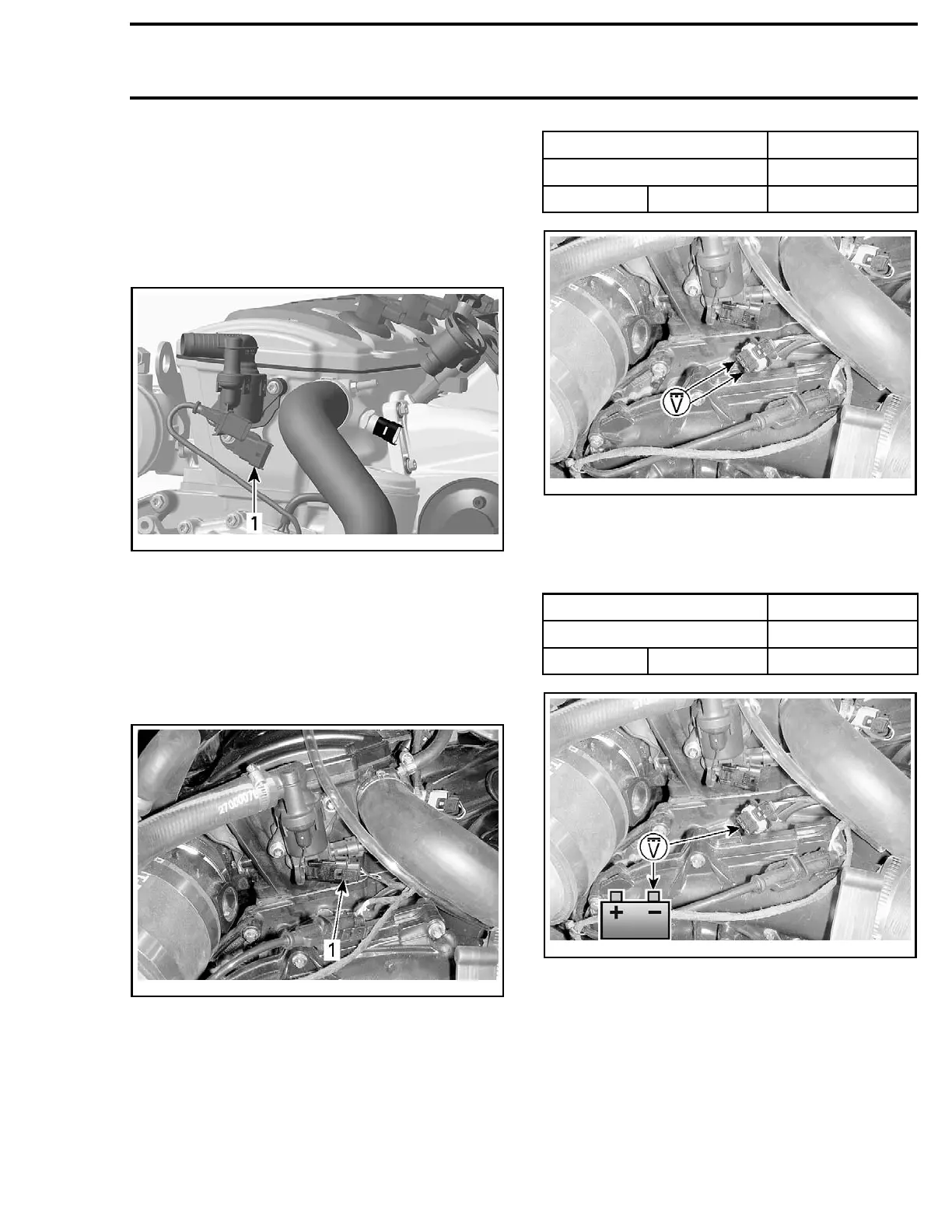
CAMSHAFT POSITION SENSOR
(CAPS)
smr2006-020-057_a
TYPICAL
1. CAPS
CAPS Voltage Test (Harness Side)
First check fuse F2 in fuse box #1 (FB).
To gain access to the CAPS, remove the required
parts as described in
CAPS REPLACEMENT.
Disconnect CAPS connector.
smr2009-030-034_a
1. CAPS co
nnector
Install D.E.S.S. key.
Briefly
press the START button to wake up the
ECM.
Probe terminals as shown.
CAPS CONNECTOR MEASUREMENT
PIN VOLTAGE
3
1
Battery voltage
smr2009-030-035_a
If battery voltage is read, proceed with
CAPS DY-
NAMIC TEST
further.
If battery voltage is not read, probe circuit as
shown.
CAPS CONNECTOR MEASUREMENT
PIN VOLTAGE
3 Battery ground Battery voltage
smr2009-030-035_b
If voltage is now read, check ground circuit be-
tween CAPS pin 1 and ECM pin A-D4 for continu-
ity. Repair wire/connector if defective.
If voltage is still not read, check power supply cir-
cuit for continuity as follows.
Remove cover of fuse box #1. Refer to
POWER
DISTRIBUTION
.
Remove the long bus bar.
smr2009-030 243

 Loading...

