Section 05 ELECTRICAL SYSTEM
Subsection 05 (STARTING SYSTEM)
NOTE: The solenoid may be the cause of a burnt
fuse (F4).
If fuse is good, proceed with the
STARTER QUICK
TEST
.
ENGINE START/STOP SWITCH
Start/Stop Switch Operation Test
Open the front storage cover and remove the stor-
age bin.
Lift suspension using the iS up button.
NOTE: If more height is required or if the iS can-
not be used, manually lift suspension by the an-
chor points close to handlebar and safely block in
this position.
NOTICE
Stop lifting as soon as suspension
has fully extended.
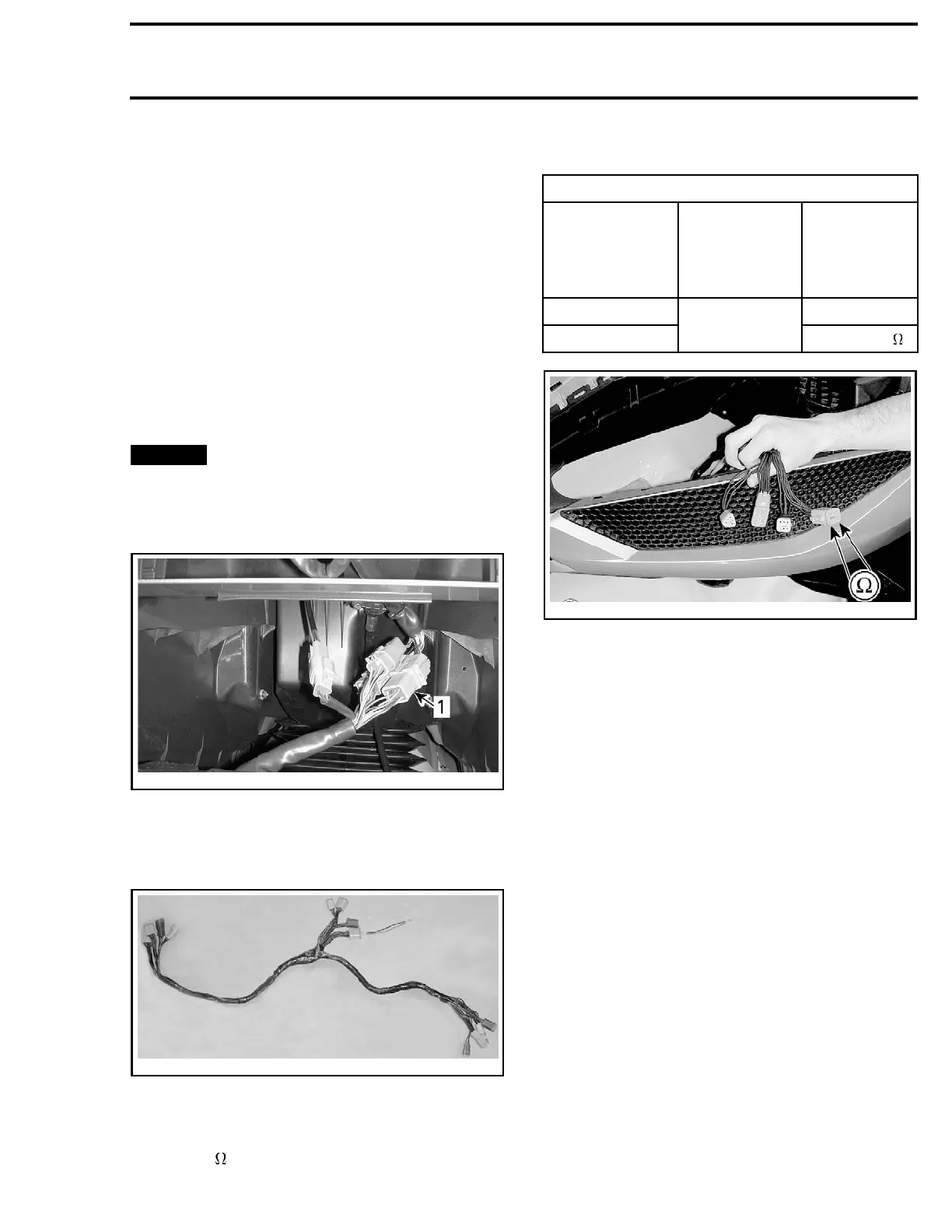
Disconnect the 8-pin connector below the moving
deck in the steering area.
smr2009-042-005_b
1. 8-pin connector here
Connect the DIAGNOSTIC HARNESS (P/N 529 036
179)
to make an in-line connection between the
disconnected connector.
529036179
NOTE: P
lug only the connector that has been dis-
conne
cted.
Use the
FLUKE 115 MULTIMETER (P/N 529 035 868)
and select .
Measure resistance through switch as per follow-
ing table.
START/STOP SWITCH OPERATION TEST
SWITCH
POSITION
8-PIN
CONNECTOR
OF
DIAGNOSTIC
HARNESS
RESISTANCE
Released
Infinite (OL)
Pressed and h
eld
Pins 1 and 2
Closeto0
smr2009-030-033_d
If switch does not test as specified, replace the
engine START/STOP switch.
If switch tests as specified, perform the
START/STOP SWITCH INPUT VOLTAGE TEST
.
Start/Stop Switch Input Voltage Test
Keep the same test setup as for the
START/STOP
SWITCH OPERATION TEST
.
Use the
FLUKE 115 MULTIMETER (P/N 529 035 868)
and select Vdc.
Measure voltage as per following table.
smr2009-034 315

 Loading...

