Section 05 ELECTRICAL SYSTEM
Subsection 05 (STARTING SYSTEM)
Disconnect starter power cable.
Remove starter retaining screws.
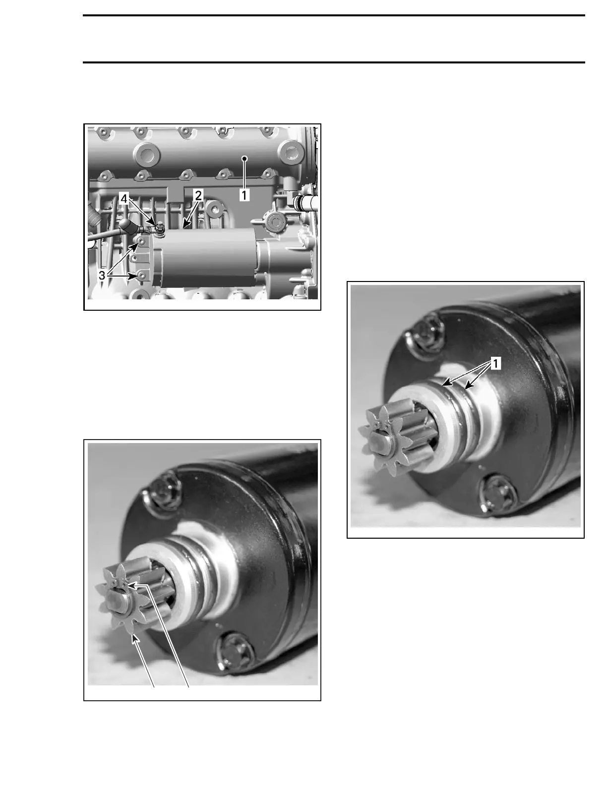
smr2007-025-008_a
TYPICAL — R
EAR OF WATERCRAFT IN ON RH SIDE OF
ILLUSTRATION
1. Exhaust manifold
2. Starter
3. Starter retaining screws
4. Starter power cable retaining nut
Starter G
ear Removal
Remove starter.
Remove gear retaining circlip and pull out starter
gear.
1
F18H0NA
2
1. Retaining circlip
2. Starter gear
Starter Gear Installation
Installation is the reverse of removal procedure.
However, pay particular attention to the following.
Use a new circlip.
Starter Installation
Installation is the reverse of the removal proce-
dure. However, pay particular attention to the fol-
lowing.
Ensure starter and engine mating surfaces are
free of debris. Serious problems may arise if
starter is not properly aligned.
Apply
ISOFLEX GREASE TOPAS NB 52 (P/N 293 550
021)
on starter O-rings.
smr2007
-025-009_a
1. Apply Isoflex grease Topas NB 52
Install starter.
NOTE: If starter does not mesh properly with
the intermediate gear: Pull starter out, slightly
rotate the starter gear then reinstall the starter.
Temporarily removing both O-rings makes it eas-
ier to align both gears. Once gears are aligned,
remove starter to install O-rings being careful not
to rotate starter gear out of position, then reinstall
the starter.
Apply
LOCTITE 243 (BLUE) (P/N 293 800 060) on re-
taini
ng screws and torque to 10 N•m (89 lbf•in).
Connect the RED positive cable to the starter and
torque retaining nut to 7 N•m (62 lbf•in).
smr2009-034 323

 Loading...

