Section 02 ENGINE
Subsection 10 (CYLINDER HEAD)
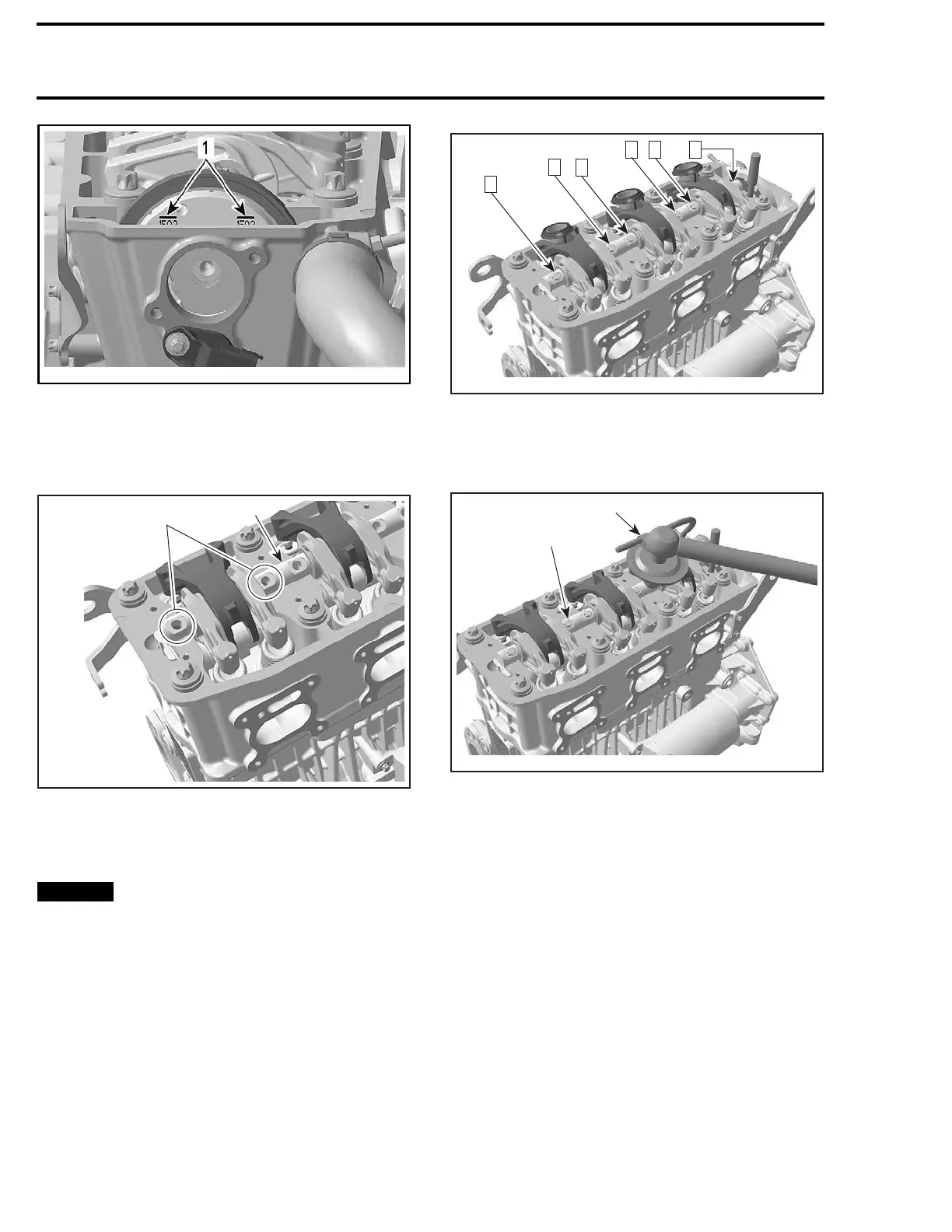
smr2009-025-006_a
1. Position lines
3. Apply engine oil on rocker arm shaft.
4. Position the rocker arm shaft with the notches
on top.
1
R1503motr91A
2
1. Rocker arm shaft
2. Rocker arm shaft notches
5. Inst
all NEW rocker arm shaft screws. Torque as
per f
ollowing procedure:
NOTICE
This assembly uses stretch screws.
As the screws have been stretched from the
previous installation, it is very important to
use new screws at assembly. Failure to re-
place screws and to strictly follow the torque
procedure may cause screws to loosen and
lead to engine damage.
6. Torque screws at first to 10 N•m (89 lbf•in) ac-
cording to following sequence.
R1503motr93A
2
1 3 4
5
6
7. Retorque screws to 20 N•m (15 lbf•ft).
8. Finish tightening screws turning an additional
90° rotation with a torque angle gauge.
1
R1503motr92A
2
1. Rocker arm shaft screw
2. Torqu
e angle gauge
CAMSH
AFT TIMING GEAR
NOTE: Although it is not necessary to position
crankshaft to TDC for disassembly, it is a good
practice to do it, as a troubleshooting step, to
know before disassembly if valve timing was
appropriate.
Cams
haft Timing Gear Removal
Lock crankshaft, refer to
CYLINDER BLOCK
sub-
section.
Remove
CYLINDER HEAD COVER
, see proce-
dure above in this subsection.
Lock
camshaft. Refer to
CAMSHAFT
in this sub-
sect
ion.
Remove the oil separator cover. Refer to
LUBRI-
CATION SYSTEM
subsection.
136 smr2009-025

 Loading...

