Section 04 FUEL SYSTEM
Subsection 02 (ELECTRONIC FUEL INJECTION (EFI))
Using a multimeter and the ECM ADAPTER TOOL
(P/N 529 036 166)
, check the resistance of circuit
A-B4, A-G4 and A-H2.
If wiring harness is good, check ECM. Refer to
ENGINE CONTROL MODULE (ECM)
in this sec-
tion.
Otherwise, repair the connectors or replace the
wiring harness between ECM connector and the
MAPS.
MAPS Replacement
Open seat.
Remove rear ventilation box. Refer to
AIR INTAKE
SYSTEM
.
Remove deck extension. Refer to
BODY
.
Disconnect MAPS connector and remove the
MAPS.
Install the new MAPS paying attention to index
its tab into the adaptor notch. Apply Loctite 243
(blue) on screw then torque to 10 N•m (89 lbf•in).
Reinstall remaining removed parts.
EXHAUST GAS TEMPERATURE
SENSOR (EGTS)
smr2009-030-040_a
1. Muffler
2. Exhaust gas temperature sensor (EGTS)
NOTE: Overheat signals will appear when ex-
haust temperature reaches:
ENGINE TEMPERATURE
All 1503
110°C (230°F)
EGTS Res
istance Test
To gain access to the EGTS, remove the required
parts as described in
EGTS REPLACEMENT.
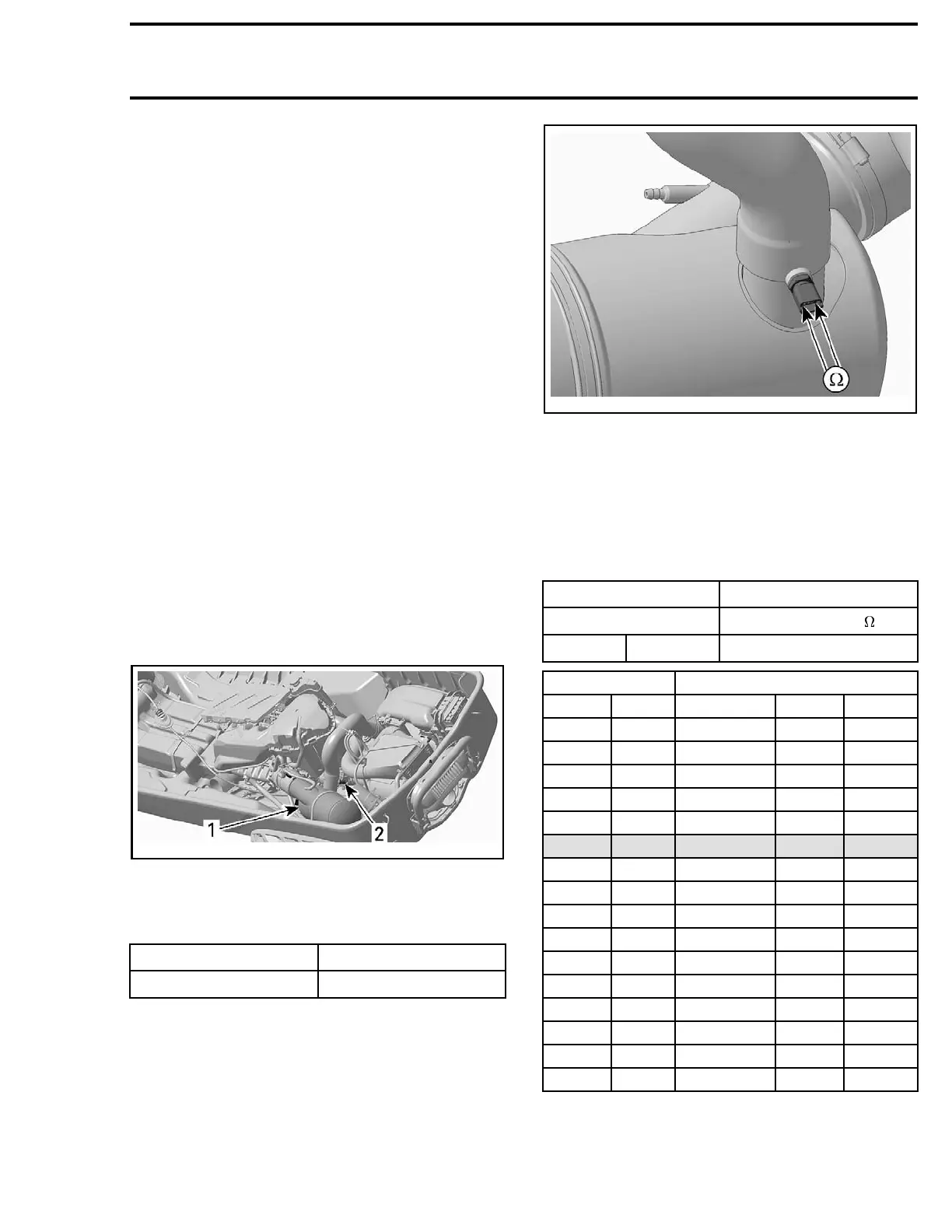
Disconnect the connector from the EGTS and
check the resistance of the sensor itself.
smr2008-023-018_a
The resistance should be as per following chart.
Otherwise, replace the EGTS.
If resistance tests good, reconnect the EGTS and
disconnect the ECM connector A on the ECM.
Using a multimeter and the
ECM ADAPTER TOOL
(P/N 529 036 166)
, check the circuit resistance as
per following table.
ECM ADAPTE
R
MEASUREME
NT
PIN RESISTANCE
A-J4 A-H4
See table below
TEMPERATURE RESISTANCE (OHMS)
°C °F NOMINAL LOW HIGH
- 30 - 22 12600 11800 13400
-20
-4
11400 11000 11800
-10
14
9500 8000 11,000
0 32 5900 4900 6900
10 50 3800 3100 4500
20 68 2500 2200 2800
30 86 1700 1500 1900
40 104 1200 1080 1320
50 122 840 750 930
60 140 630 510 750
70 158 440 370 510
80 176 325 280 370
90 194 245 210 280
100 212 195 160 210
110 230
145
125 160
120 248
115
100 125
smr2009-030 249

 Loading...

