Section 06 STEERING AND PROPULSION
Subsection 01 (STEERING AND O.T.A.S.)
STEERING
POSITION
MULTIMETER
LEAD
POSITION
RESISTANCE
Center position
1935 - 2365
Fully turned
Pin "C" and
vehicle ground
324 - 396
If continuity test is out of specification, try any
good magnet and bring it in front of the switch. If
continuity test is now good, replace the magnets.
If continuit
y test is still out of specification with a
new magnet, c
heck wires, connectors and termi-
nals. If all
is good, replace the O.T.A.S. switch.
O.T.A.S. Switch Replacement
1. Remove
STEE
RING COLUMN SUPPORT
,see
procedure i
n this subsection.
2. Remove steering column from its support by
removing both retaining screws.
smr2009-037-027_a
1. Steering column screws
3. Using a
small screwdriver, unlatch the switch
from st
eering support.
smr2009-037-038_a
1. Switch retaining tabs
Reverse removal procedure to reinstall the
O.T.A.S. switch.
O.T.A.S. MAGNETS
Magnets Replacement
1. Remove
STEERING COLUMN
, see procedure
in this subsection.
2. Remove wiring harness from the center of
steering column.
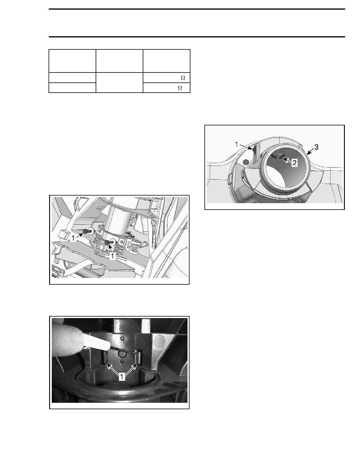
3. Using a long tool, press on retaining tabs to re-
lease the magnets.
smr2009-037-039_a
1. Magnets
2. Retaining tabs
3. Lower end of steering column
Reverse removal procedure to reinstall the mag-
nets.
smr2009-037 371

 Loading...

