Section 02 ENGINE
Subsection 11 (CYLINDER BLOCK)
1
R1503motr30A
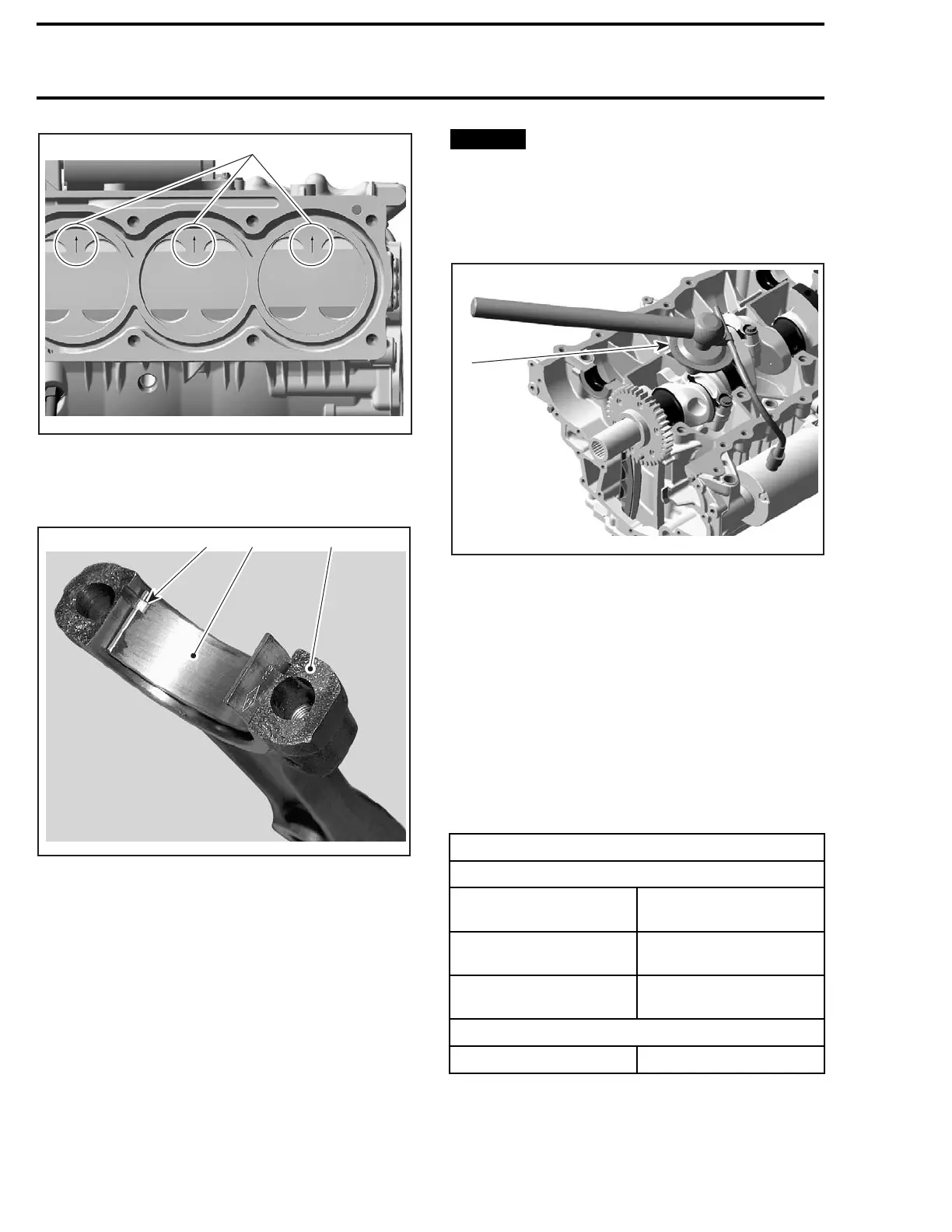
1. Arrow toward exhaust side
2. Correctly install bearings and carefully clean
split surface on both sides (cracked area).
3
R610motr79A
12
1. Half bearing of connecting rod big end
2. Spli
t surface of the connecting rod
3. Protrusion of bearing in line with connecting rod groove
3. Torque NEW connecting rod screws no. 11 as
per following procedure:
3.1 Install screws and torque to 45 N•m
(33 lbf•ft). Do not apply any threadlocker
product.
3.2 Fin
ish tightening the screws with an ad-
di
tional 90° turn using an angle torque
wr
ench.
NOTICE
Failure to strictly follow this proce-
dure may cause screw to loosen and lead to
engine damage. Knowing that the screws have
been stretched from the previous installation,
it is very important to use new screws at as-
sembly.
R1503motr31A
1
1. Angle to
rque wrench
PISTON R
INGS
Piston Ring Removal
Remove p
iston as described above.
Remove rings.
Piston R
ing Inspection
Ring/Piston Groove Clearance
Using a feeler gauge measure each ring/piston
groove clearance. If the clearance is too large, the
piston and the piston rings should be replaced.
RING/PISTON GROOVE CLEARANCE
NEW
RECTANGULAR
0.025 mm - 0.070 mm
(.001in - .0028 in)
TAPER-FACE
0.015 mm - 0.060 mm
(.0006 in - .0024 in)
OIL SCRAPER RING
0.020 mm - 0.055 mm
(.0008 in - .0022 in)
SERVI
CE LIMIT
ALL
0.15 mm (.006 in)
158 smr2009-026

 Loading...

