Section 07 BODY AND HULL
Subsection 02 (BODY)
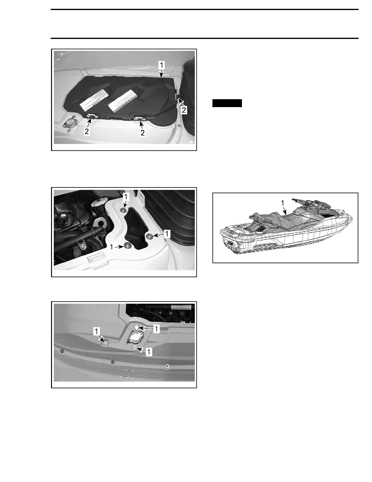
smr2009-016-001_a
1. Vent box
2. Retaining latches
3. Remove screws securing air inlet to deck ex-
tension.
smr2009-042-020_a
1. Air inlet retaining screws
4. Remove coolant reservoir screws.
smr2009-042-021_a
1. Cool
ant reservoir screws
5. Remove all screws retaining deck extension to
fixed deck.
6. Clo
se seat.
7. Tilt the
MOVING DECK
, see procedure in this
subsection.
8. Remove the deck extension.
Deck Extension Installation
1. Position the deck extension.
2. Install screws retaining deck extension and air
inlet.
3. Tighten these screws to 1.5 N•m (13 lbf•in).
NOTICE
Do not tighten screws over this
recommended torque. Otherwise, the rubber
grommet could turns and screw will be hard
to remove.
4. Install coolant reservoir screws and tighten
them to 5 N•m (44 lbf•in).
5. Reposition moving deck. Refer to
MOVING
DECK
in this subsection.
MOVING DECK
smr2009-
042-008_a
1. Moving deck
The moving deck is comprised of:
– Front st
orage cover
– Front body module
– Steering
–Seat
– Foot wells.
The mov
ing deck is attached to the intelligent sus-
pensio
n and moves as a single unit.
The moving deck does not comprise the boarding
platform and the rear storage bins.
It is possible to tilt the moving deck for servicing
the watercraft, such as:
– Deck extension removal
–Worki
ng on air intake system
– Suspension position sensor replacement
– Suspension hydraulic pump replacement.
The moving deck removal is also required for ma-
jor repairs, such as:
– Engine removal
–Susp
ension component removal (except sus-
pens
ion position sensor)
– Fuel tank removal.
smr2009-042 469

 Loading...

