Section 02 ENGINE
Subsection 10 (CYLINDER HEAD)
NOTICE
Each installation of the cylinder
head requires a new cylinder head gasket. Us-
ing a gasket twice will cause engine damage,
even if the engine had not run.
Apply
LOCTITE 243 (BLUE) (P/N 293 800 060) on
threads of screws M6.
Install screws M6 and manually tighten them.
Install NEW screws M11and tighten them manu-
ally.
NOTICE
This assembly uses stretch screws.
As the screws M11 have been stretched from
the previous installation, it is very important to
replace the old screws by new ones at assem-
bly. Failure to replace screws and to strictly fol-
low the torque procedure may cause screws to
loosen and lead to engine damage.
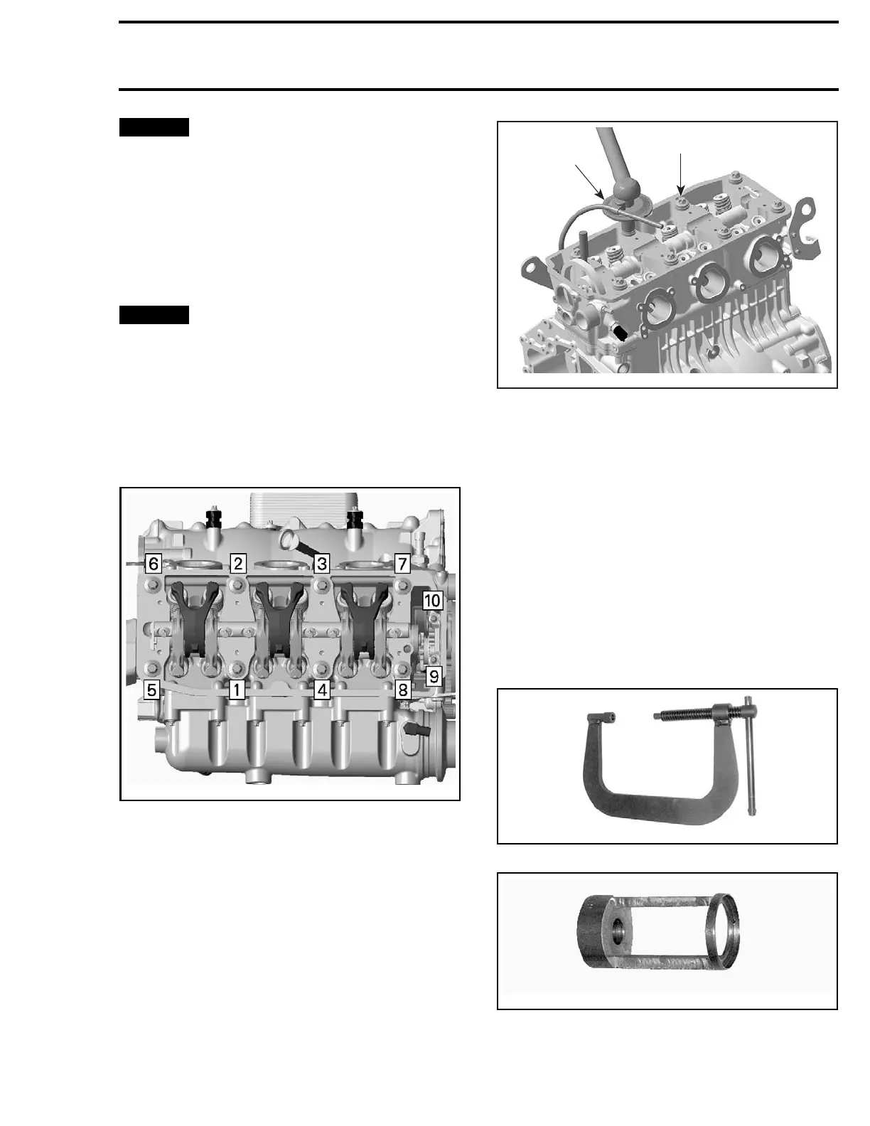
Using the following sequence, tighten screws as
described below.
smr2005-036-002_a
1. First t
orque screws M11 to 40 N•m (30 lbf•ft).
2. Then tighten screws M11 turning a 120° rota-
tion with a torque angle gauge and finish tight-
ening with an additional 90° rotation.
3. Torque screws M6 to 9 N•m (80 lbf•in).
1
R1503motr100A
2
1. Cylinder screws M11
2. Angle torque wrench
Remove all locking tools.
Install all removed parts.
VALVE SPRINGS
Valve Spring Removal
Remove rocker arm shaft. Refer to
ROCKER ARM
procedure in this subsection.
Remove
CYLINDER HEAD
, see procedure in this
subsection.
Compress valve springs, using the
VALVE SPRING
COMPRESSOR (P/N 529 035 724)
and the VALVE
SPRING COMPRESSOR CUP (P/N 529 036 073)
.
5290357242
VALVE SPRING COMPRESSOR
529036
073
VALVE SPRING COMPRESSOR CUP
smr2009-025 141

 Loading...

