Section 06 STEERING AND PROPULSION
Subsection 01 (STEERING AND O.T.A.S.)
GENERAL
During assembly/installation, use torque values
and service products as in the exploded view.
Clean threads
before applying a threadlocker. Re-
fer to
SELF-LO
CKING FASTENERS
and
LOCTITE
APPLICATION
a
t the beginning of this manual for
complete proc
edure.
WARNING
Torque wrench tightening specifications
must be strictly adhered to.
Locking devices (e.g.: locking tabs, elastic
stop nuts, self-locking fasteners, cotter pins,
etc.) must be replaced with new ones.
Hoses, cables or locking ties removed during a
procedure must be reinstalled as per factory stan-
dards.
SYSTEM DESCRIPTION (O.T.A.S.)
The O.T.A.S. (Off-Throttle Assisted Steering) pro-
vides additional maneuverability in off-throttle sit-
uations.
The system uses a pair of magnets mounts on the
steering column and a Hall effect switch mounts
underneath steering column support.
When activated by a magnet, the O.T.A.S. switch
sends a signal to the ECM.
The ECM activates a pre- programmed RPM set-
ting when the driver initiates a full turn after relea-
sing throttle lever. The engine RPM is controlled
by the intelligent Throttle Control (iTC).
The O.T.A.S. system is activated when the follow-
ing conditions are achieved:
– The engine speed must be above 4000 RPM for
at least 1.5 second (approximately).
– The throttle lever must be released completely.
– The steering must be fully turned within approx-
imately 4 seconds after throttle release.
The O.T.A.S. will stay activated for a random
period of time as long as the O.T.A.S. switch is
closed.
O.T.A.S. will be deactivated if:
– The throttle is reapplied, or
– The steering is turned sufficiently to open the
O.T.A.S. switch for more than one second.
ADJUSTMENT
STEERING ALIGNMENT
Raise the iBR gate by activating the iBR override
function. Refer to
IBR AND VTS
subsection.
Install two bu
ngee cords to maintain steering dur-
ing the proced
ure.
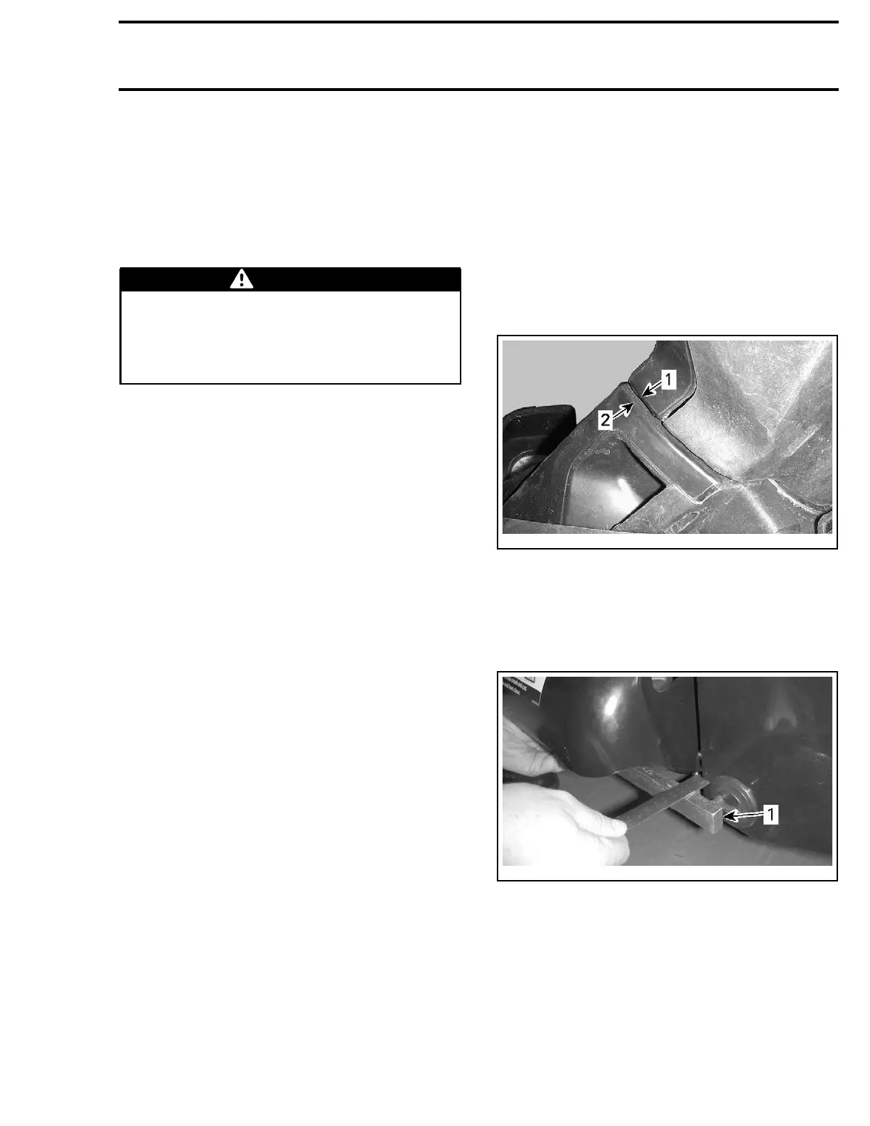
Position steering so that the edge of the steering
column cover and edge of the gauge support are
equal.
smr2009-037-055_a
1. Steering column cover edge
2. Gauge support edge
Check jet pump nozzle position by placing a
straight edge on nozzle outer end. Measure the
distance on each side of the straight edge. It
must be equalled.
smr2009-037-003_a
1. Straight edge places against nozzle
If nec
essary, steering alignment adjustment
shoul
d be performed at steering column.
Open storage compartment cover and remove
basket.
Loosen steering column clamp bolts securing the
steering cable clamp at the bottom of steering col-
umn.
Turn a
djusting nut as required.
smr2009-037 361

 Loading...

