Section 09 WIRING DIAGRAM
Subsection 02 (CONNECTOR INFORMATION)
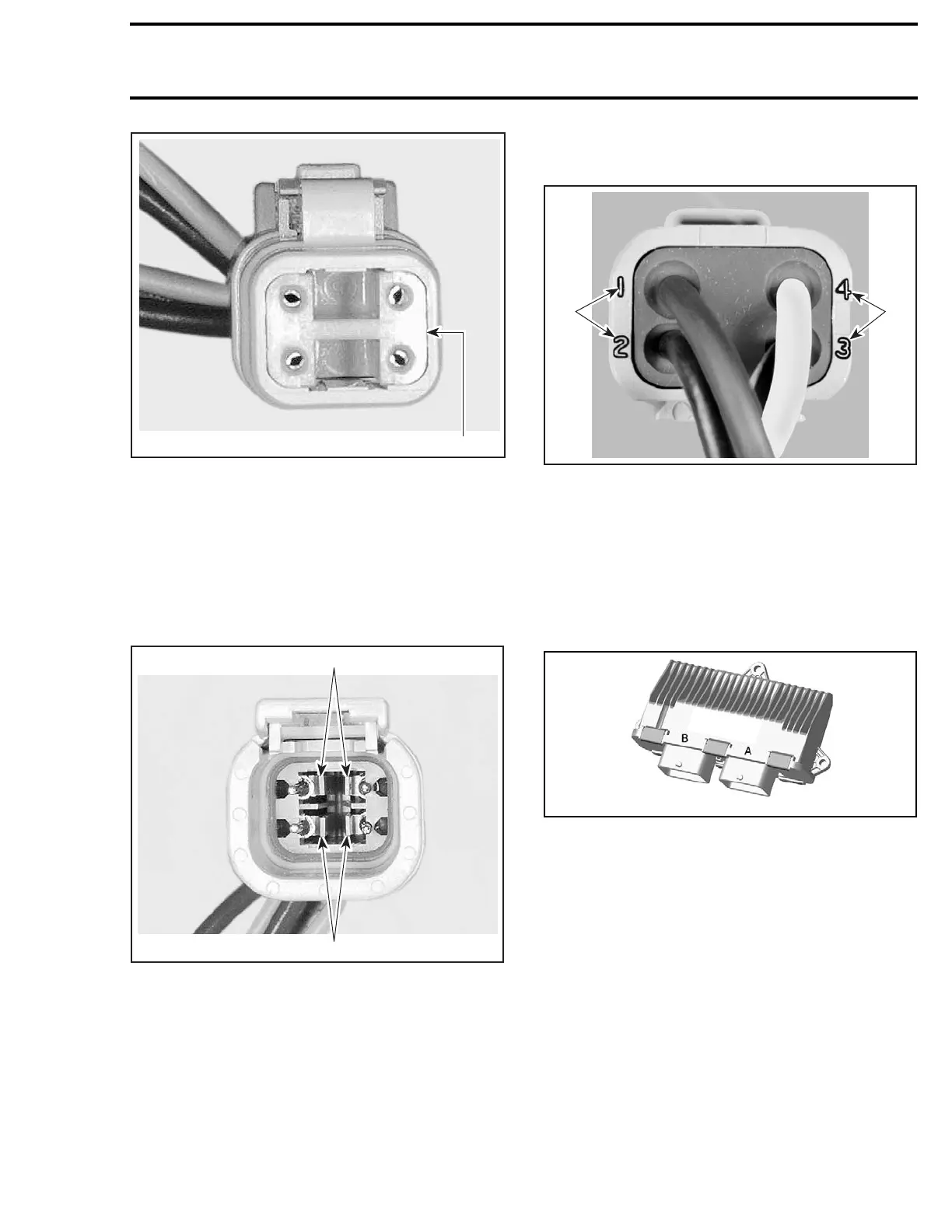
V01G0PA
1
MALE CONNECTOR
1. Male lock
NOTE: Before extraction, push wire forward to re-
lieve pressure on retaining tab.
1. Insert a 4.8 mm (.189 in) wide screwdriver
blade inside the front of the terminal cavity.
2. Pry back the retaining tab while gently pulling
wire back until terminal is removed.
V01G0QA
1
1
FEMA
LE CONNECTOR
1. Retaining tabs
To install:
3. For insertion of a terminal, make sure the lock
is removed.
4. Inse
rt terminal into appropriate cavity and push
as fa
rasitwillgo.
5. Pull back on the terminal wire to be sure the
retention fingers are holding the terminal.
6. After all required terminals have been inserted,
the lock must be installed.
F04H6LA
1 1
1. Wire identification numbers
ECM CONNECTOR (MOLEX)
There are 2 connectors on the ECM. The engine
wiring harness connector is connected on the
ECM connector A and the vehicle wiring harness
connector is connected to the ECM connector B.
Each ECM connector has 48 pins.
smr2009-027-005
ECM CON
NECTORS
ECM Connector Removal
To reac
h ECM connector, refer to
ELECTRONIC
FUEL IN
JECTION
subsection.
Push and hold the locking tab of the desired con-
nector.
smr2009-044 521

 Loading...

