Section 09 WIRING DIAGRAM
Subsection 02 (CONNECTOR INFORMATION)
F18Z0NA
1
2
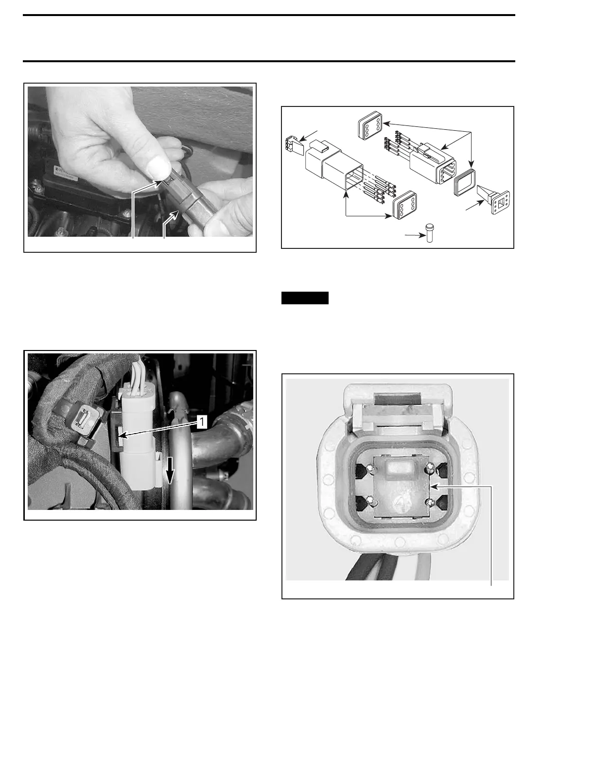
TYPICAL
1. Deutsch connectors
2. Press release button
Engine Connector
Insert a small flat screwdriver between the sup-
port and the Deutsch connectors. Pry while slid-
ing out connectors in the direction shown.
smr200
9-045-010_a
MALE CONNECTOR REMOVED FOR CLARITY PURPOSE
1. Insert screwdriver here
Connector Disassembly
F00H1CA
1
3
4
2
3
1. Male connector
2. Female connector
3. Secondary lock
4. Sealing cap
NOTICE
Do not apply dielectric grease on ter-
minal inside connector.
To remove terminals from connector, proceed as
follows:
– Using a long nose pliers, pull out the lock.
1
V01G0OA
FEMA
LE CONNECTOR
1. Female lock
520
smr2009-044

 Loading...

