Section 06 STEERING AND PROPULSION
Subsection 04 (DRIVE SHAFT)
GENERAL
The jet pump must be removed to replace any
component of the drive system. Refer to
JET
PUMP
for removal procedure.
During assemb
ly/installation, use torque values
and service pr
oducts as specified in the exploded
view.
Clean threads before applying a threadlocker. Re-
fer to
SELF-LOCKING FASTENERS
and
LOCTITE
APPLICATION
at the beginning of this manual for
complete procedure.
WARNING
Torque wren
ch tightening specifications
must be stri
ctly adhered to.
Locking dev
ices (e.g.: locking tabs, elastic
stop nuts, s
elf-locking fasteners, cotter pins,
etc.) must
be replaced with new ones.
TROUBLESHOOTING
DIAGNOSTIC TIPS
Leaks at PTO Seal
If water enters engine, or oil leaks from engine at
PTO seal, check if drive shaft is fully engaged in
sealing ring.
Compress the drive shaft boot to visually check
for proper contact.
smr2009-010_a
1. Drive shaft boot
Rubbe
r sealing lip of drive shaft must be fully en-
gaged
into flange of sealing ring.
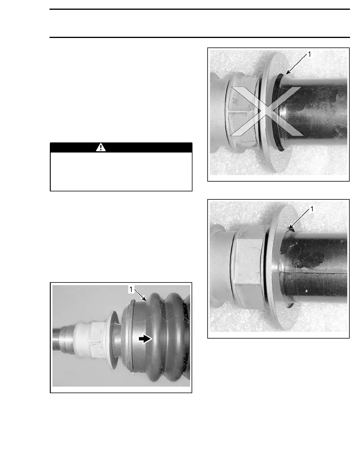
smr2009-007-012_a
WRONG
1. Rubber sealing lip NOT fully engaged
smr2009-007-013_a
CORRECT
1. Rubber sealing lip fully engaged
NOTE: If drive shaft boot cannot be compressed
enough for the inspection, remove jet pump and
torque drive shaft. If this does not work, remove
drive shaft and inspect drive shaft threads. Refer
to
DRIVE SHAFT
in this subsection.
smr2009-040 429

 Loading...

