Section 07 BODY AND HULL
Subsection 01 (SUSPENSION (iS))
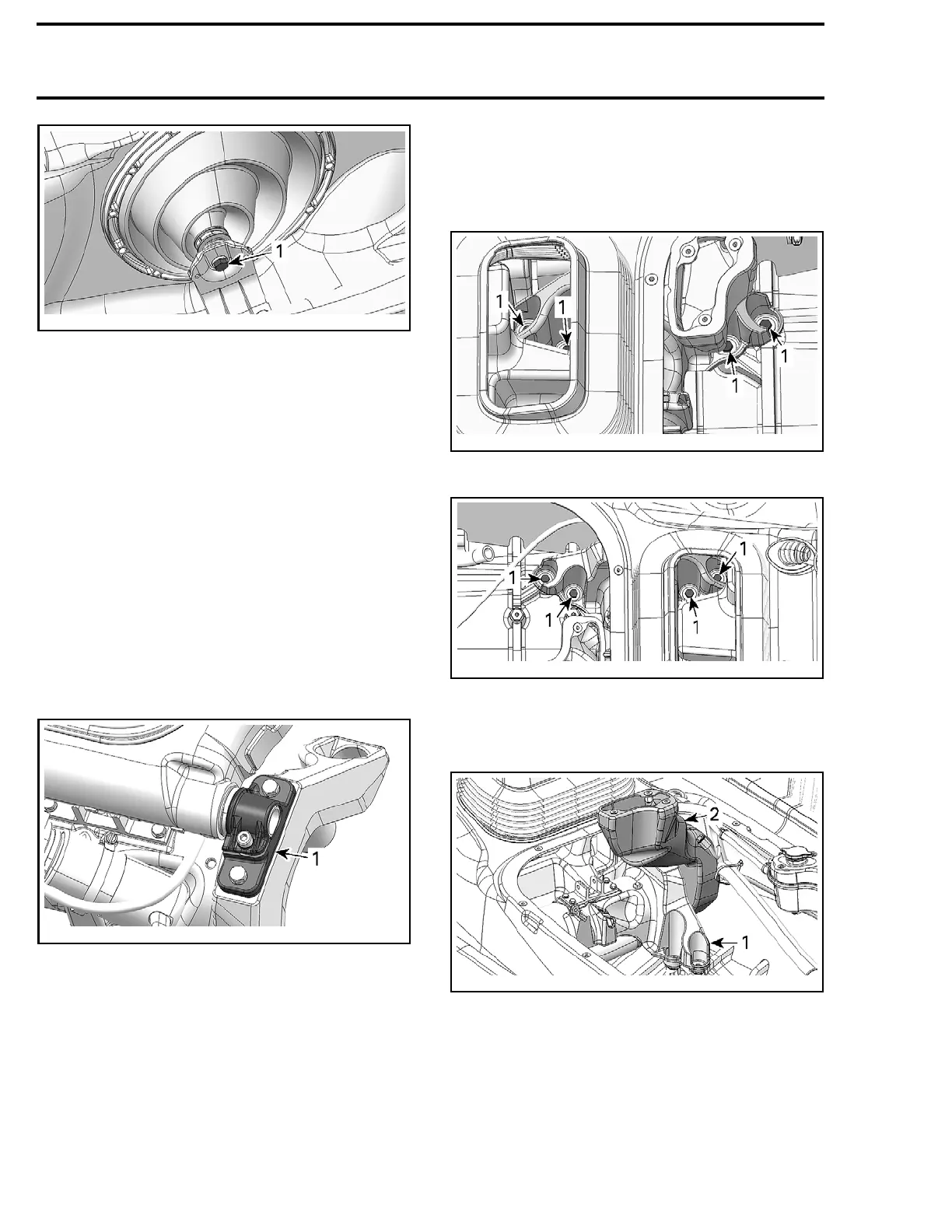
smr2009-041-024_a
RH SIDE SHOWN
1. Lateral support screw
4. Decouple lateral supports from suspension arm
shaft.
5. Refer to
HYDRAULIC PUMP REMOVAL (AS A
UNIT WITH ACTUATOR)
and remove the pump
from the vehicle.
6. Remove screws securing both shaft supports
to suspension base.
7. Move front suspension arm rearward to re-
move it from the vehicle.
Front Suspension Arm Installation
The installation is the reverse of the removal pro-
cedure. However, pay attention to the following.
If a shaft support has been loosen from the
suspension arm shaft, see
SUSPENSION ARM
SHAFTS
for proper installation procedure.
smr20
09-041-063_a
1. Shaft support (one on each side)
SUSPENSION BASE
Suspension Base Removal
1. Refer to the appropriate procedures and re-
move the following parts:
– Moving deck
–Engi
ne
– Shock absorber and springs
– Hydraulic pump (with actuator)
–Sus
pension position sensor.
2. Using a marker, trace the shape of suspension
base at the bottom of the hull to reposition it
at the same place.
3. Remove and discard suspension base screws.
smr2009-041-031_a
STARBOARD SIDE
1. Suspensio
n base screws
smr2009-041-032_a
PORT SID
E
1. Suspension base screws
4. Remove suspension base with the rear vent
duct.
smr2009-041-033_a
1. Suspension base
2. Rear vent duct
460
smr2009-041

 Loading...

