Section 07 BODY AND HULL
Subsection 03 (HULL)
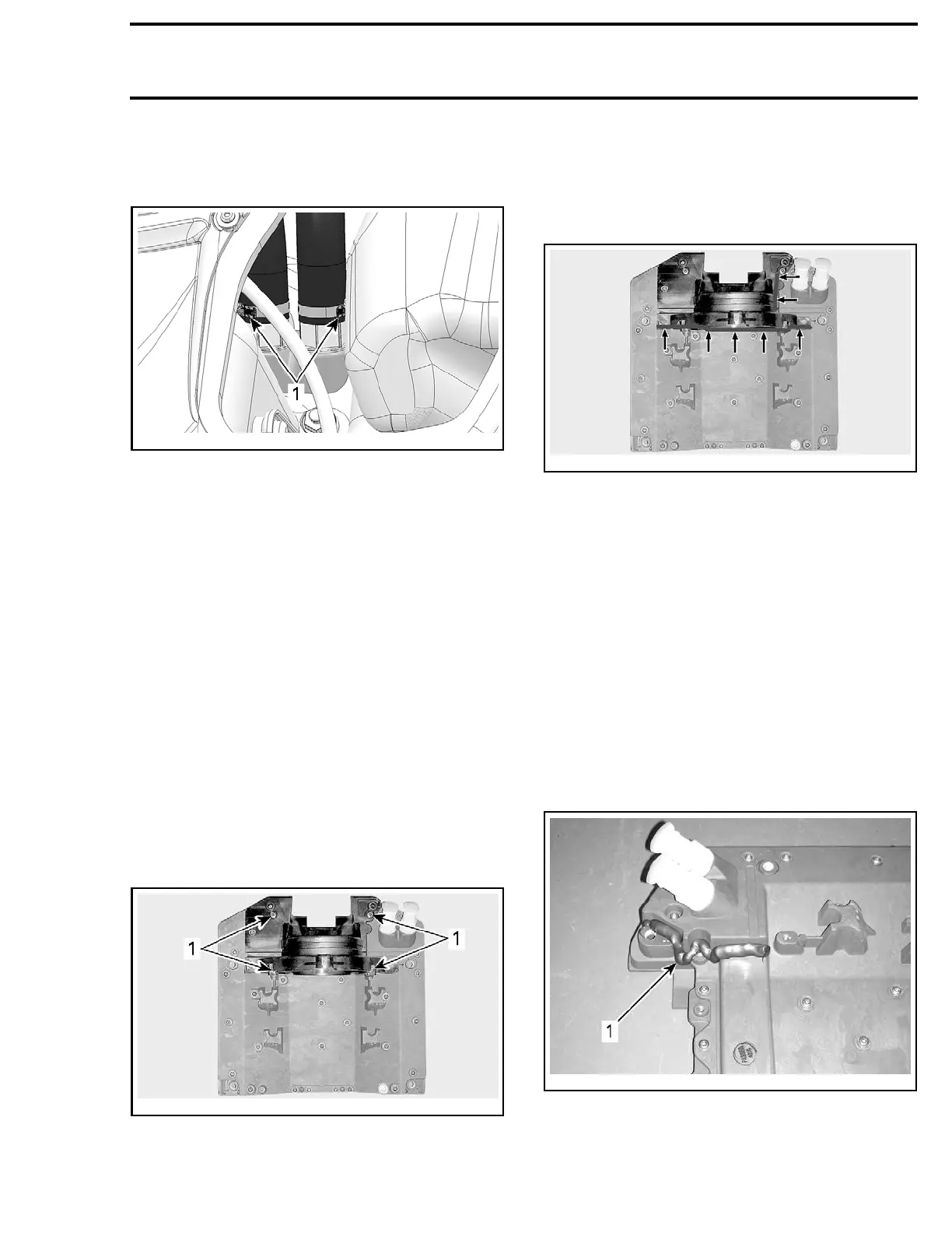
9. Reinstall coolant hoses on ride plate fittings,
pay attention to gear clamp positioning. See
following illustration.
smr2009-043-016_b
1. Gear clamp
positioning
10. Install jet pump, refer to the
JET PUMP
sub-
section.
11. Install i
BR gate and VTS trim ring, refer to the
IBR AND VT
S
subsection.
12. Install battery and electrical accessories sup-
port, refer to
CHARGING SYSTEM
subsec-
tion.
13. Refill cooling system and carry out a leak test.
Refer to
COOLING SYSTEM
subsection.
14. Instal
l all remaining parts in the reverse order
of remo
val.
JET PUM
P SUPPORT
Jet Pump Support Removal
1. Remove
the inlet grate and ride plate, see pro-
cedur
es in this subsection.
2. Remove the four screws retaining the pump
support to the ride plate.
smr2009-043-019_a
TYPICAL - TOP VIEW RIDE PLATE AND PUMP SUPPORT
1. Pump support retaining screws
3. Sealant is applied between the jet pump sup-
port and the ride plate. Using a heat gun, heat
the base of the pump support to soften the
sealant and carefully pry the pump support off
therideplate.
smr2009-0
43-019_b
APPLY HEAT HERE
Jet Pump Support Cleaning
1. Scrape off all excess sealant from jet pump sup-
port, ride plate, and hull.
2. Inspect p
ump support for cracks and other
damages.
Replace as necessary.
3. Clean jet pump support and hull surface with
BRP HEAVY DUTY CLEANER (P/N 293 110 001) to
eliminate grease, dust, and sealant residue.
Jet Pump
Support Installation
1. Ensure sealant contact areas are clean and dry.
2. Apply
LOCTITE 5900 (P/N 293 800 066) on the ride
plate and pump support as seen in the following
illustrations.
smr2009-043-021_a
1. Apply loctite 5900 here
smr2009-042 503

 Loading...

