Section 02 ENGINE
Subsection 06 (EXHAUST SYSTEM)
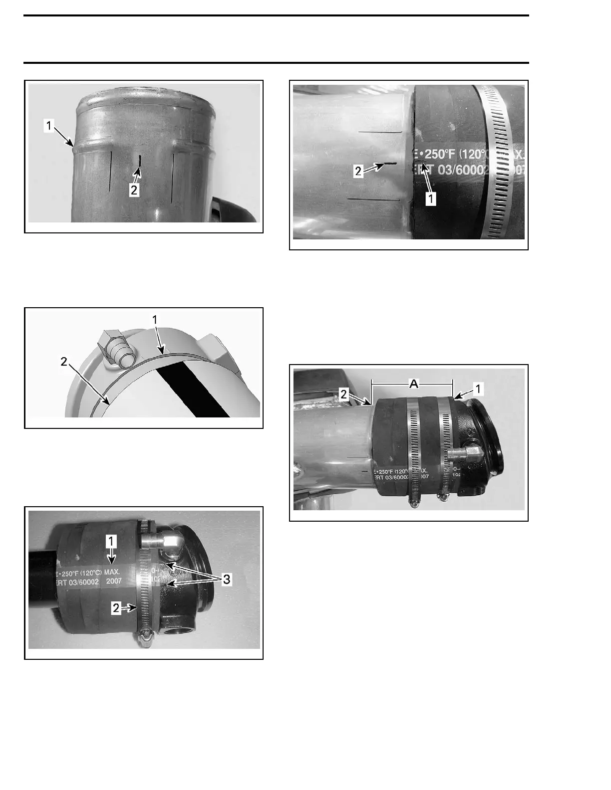
smr2008-013-035_a
1. Bulge
2. Middle of the opening
Install the rubber adapter on exhaust pipe. Ensure
rubber adapter is properly seats against exhaust
pipe shoulder.
smr2008
-013-038_a
1. Exhaust pipe shoulder
2. Rubber adapter
Center t
he rubber adapter strip of the rubber
adapte
r between both exhaust pipe marks.
Tighten retaining clamp to 8 N•m (71 lbf•in).
smr2008-013-036_a
1. Rubber adapter strip
2. Retaining clamp
3. Exhaust pipe marks
Slide the other clamp on the rubber adapter.
Insert the exhaust pipe into the muffler.
Align the center of the rubber adapter strip with
the mark previously traced on muffler.
smr2008-013-037_a
1. Middle of rubber adapter strip
2. Center of the muffler bulge opening
Using a caliper, measure the distance between
the exhaust pipe shoulder and the outside of the
muffler bulge.
Position the muffler to 95 mm ± 2 mm
(3.74 in ± .079 in). Check the distance in
several places.
smr200
8-013-039_a
1. Rubber adapter end
2. Outside of the muffler bulge
A. 95 ± 2 m
m (3.74 ± .0787 in)
Tighten retaining clamp to 8 N•m (71 lbf•in).
Insta
ll muffler in vehicle. Refer to
MUFFLER IN-
STALL
ATION
in this subsection for complete pro-
cedur
e.
EXHAU
ST MANIFOLD
Exhaust Manifold Removal
1. Remov
e the moving deck and the deck exten-
sion.
Refer to
BODY
subsection.
2. Move muffler rearwards to make room. Refer
to
MUFFLER REMOVAL
in this subsection to
know how separate muffler from exhaust man-
ifold.
66 smr2009-021

 Loading...

