Section 02 ENGINE
Subsection 10 (CYLINDER HEAD)
1
R1503motr255A
TYPICAL
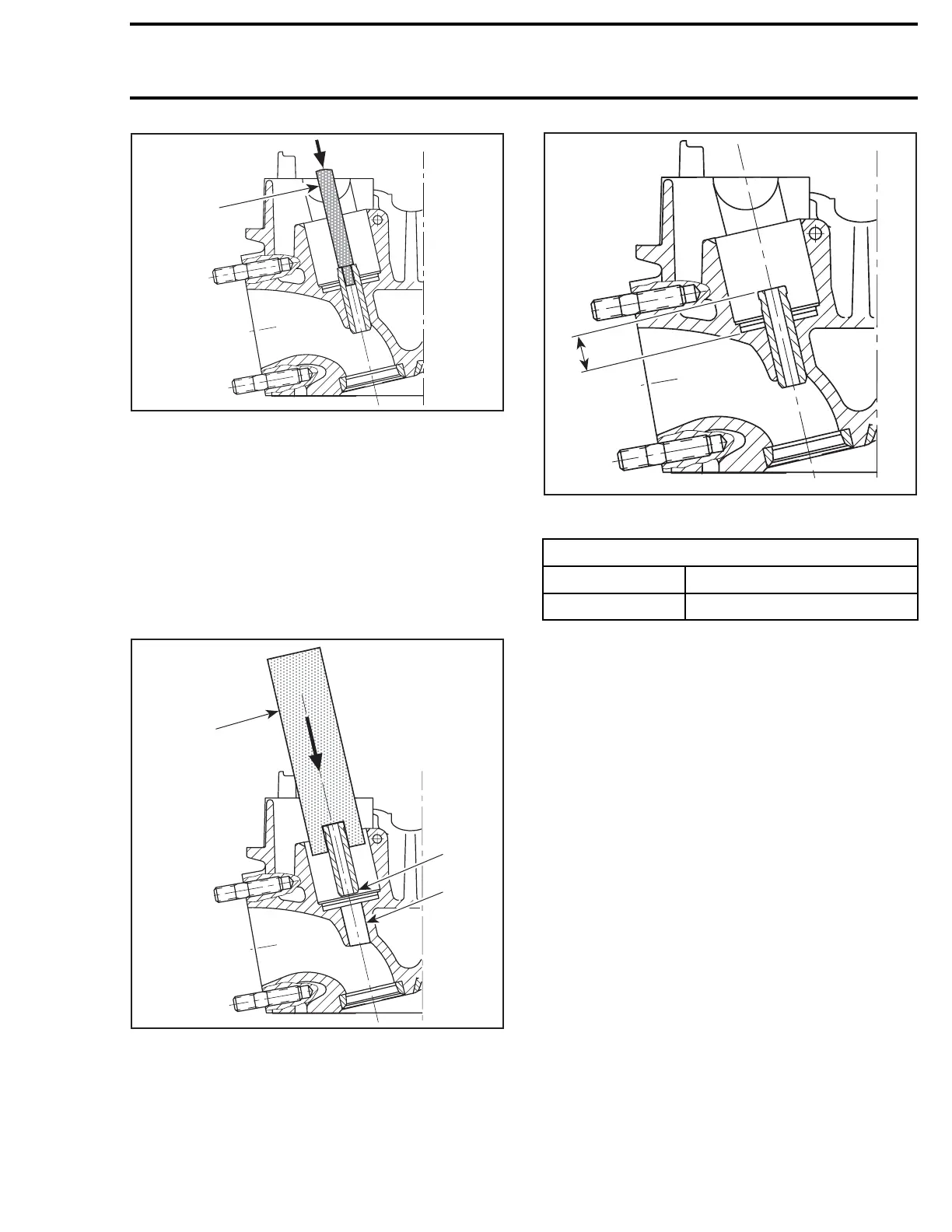
1. Punch
Check valve guide bore for abreased material.
The inlet and exhaust valve guides have the same
length and are interchangeable.
NOTE: If valve guide has caused scoring during
extraction, replace the cylinder head.
Grease the bore in cylinder head and the leading
end of valve guide with
MOLYKOTE G-N (P/N 420
297 433)
.
3
R1503motr256A
1
2
TYPICAL
1. Valve guide leading end
2. Cylinder head bore
3. Jig
With the VALVE GUIDE PUSHER (6 MM) (P/N 529 036
087)
, press the valve guide into the COLD cylinder
head as shown.
A
R1503motr257A
TYPICAL
A. Protrusion
VALVE GUIDE PROTRUSION
MINIMUM
12.4 mm (.4882 in)
MAXIMUM
12.8 mm (.5039 in)
NOTE: After installing new guides, they must be
reamed with a standard 6 mm reamer tool. These
are available from various tool suppliers.
Clean cy
linder head carefully. Check that the valve
seat is c
oncentric with the new guide axis (check
contact
surface with engineer's blue).
smr2009-025 147

 Loading...

