Section 02 ENGINE
Subsection 11 (CYLINDER BLOCK)
Remove:
– Intake manifold (refer to
INTAKE MANIFOLD
subsection)
– Spark plugs
– Cylinder head cover (refer to
CYLINDER HEAD
subsection
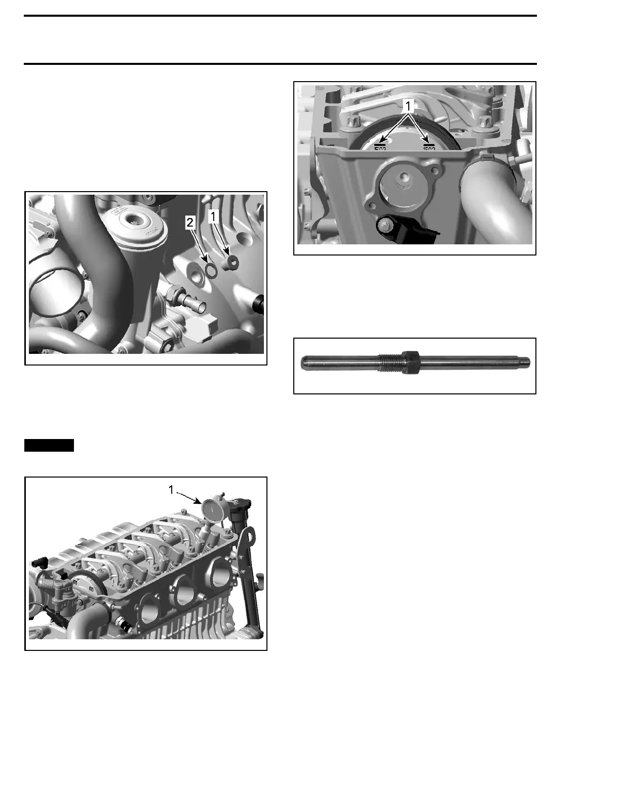
– Crankshaft access plug screw.
smr2009-
026-002_a
1. Crankshaft access plug screw
2. Gasket ring
Turn eng
ine counterclockwise.
Bring piston of cylinder no. 3 to ignition TDC, us-
ing a dial gauge or another similarly suitable tool.
NOTICE
Do not sc
ratch or damage piston and
cylinde
rsurface.
smr2009-026-003_a
1. Dial gauge
NOTE: When the piston of cylinder no. 3 is at igni-
tion TDC, the position lines on oil separator cover
must be lined up as shown in the following illus-
tration.
smr2009-026-004_a
1. Position lines
Use a small screwdriver to check if the groove in
the crankshaft is aligned with the hole.
In this position, lock the crankshaft using the
CRANKSHAFT LOCKING TOOL (P/N 529 035 821).
529035821
Crankshaft Removal
1. Drain eng
ine oil (refer to
LUBRICATION SYS-
TEM
subse
ction).
2. Remove engine from vehicle (refer to
ENGINE
REMOVAL/INSTALLATION
subsection).
3. Remove cylinder head (refer to
CYLINDER
HEAD
subsection).
4. Remove P
TO housing (refer to
PTO HOUSING
AND MAGN
ETO
subsection).
5. Remove starter gear (refer to
PTO HOUSING
AND MAGNETO
subsection).
6. Remove starter drive.
7. Remove
oil suction pump (refer to
LUBRICA-
TION S
YSTEM
subsection).
8. Remove engine mounting brackets.
9. Remove oil reservoir plug screws no. 1 with
O-ring no. 2.
160 smr2009-026

 Loading...

