Section 04 FUEL SYSTEM
Subsection 01 (INTELLIGENT THROTTLE CONTROL (iTC))
smr2009-042-005_c
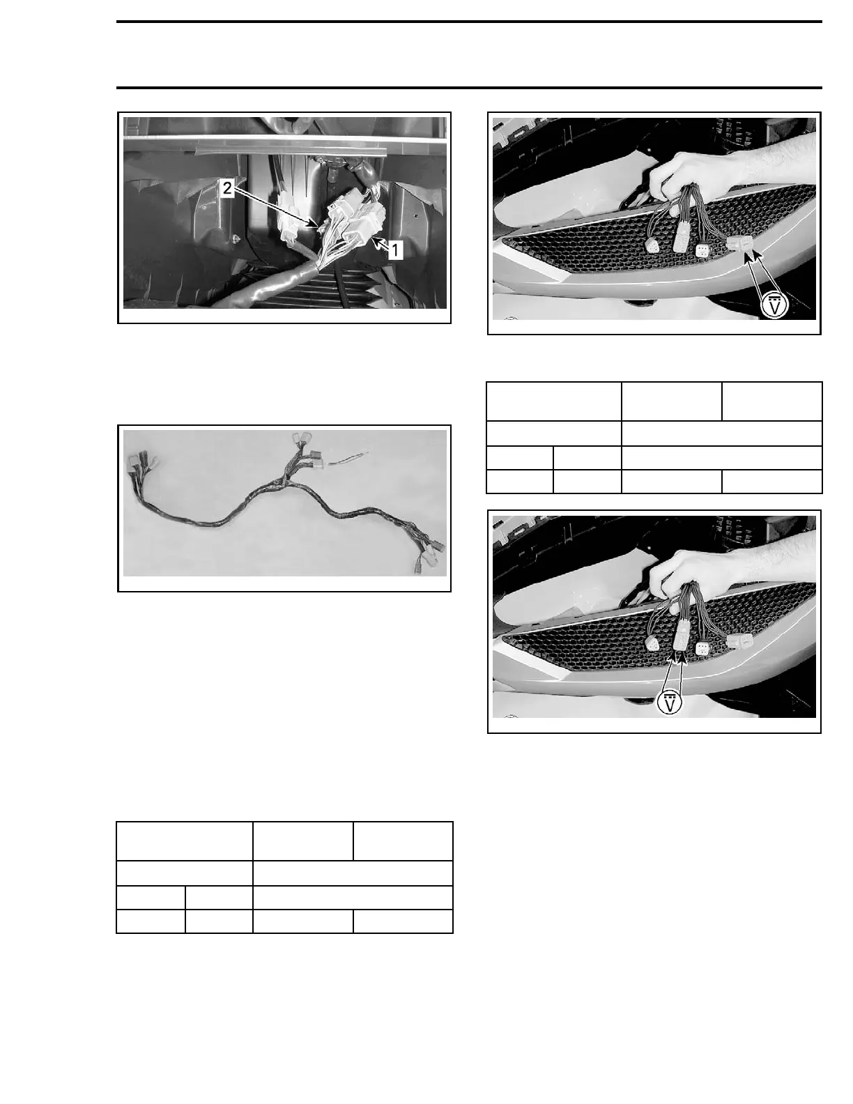
1. 8-pin conne
ctor
2. 12-pin connector
Connect the DIAGNOSTIC HARNESS (P/N 529 036
179)
to make an in-line connection between the
disconnected connectors.
529036179
NOTE: Plug only the connectors that have been
disconnected.
Install the D.E.S.S. key on its post.
BrieflypresstheSTARTbuttontowakeupthe
ECM.
Use the
FLUKE 115 MULTIMETER (P/N 529 035 868)
and select Vdc.
Measure the voltage readings on the installed di-
agnostic harness connector as follows.
Test on the 8-pin Connector of Diagnostic
Harness
8-PIN CONNECTOR IDLE POSITION
WIDE OPE
N
POSITION
PIN
VOLTAGE (Vdc)
6 7 4.9 - 5.1
7 8 0.15 - 0
.35
1.4 - 1.
6
smr2009-030-033_a
Test on the 12-pin Connector of Diagnostic
Harness
12-PIN CON
NECTOR
IDLE POSIT
ION
WIDE OPEN
POSITION
PIN
VOLTAGE (V
dc)
10 11 4.9 - 5.1
11 12 0.4 - 0.6 2.9 - 3.1
smr2009-030-033_b
Test Re
sults
If voltage is as per specification, the TAS sensor
is functional.
If voltage is out of specification, check continuity
of all wires between the ECM and the sensor. If
continuity is good, replace sensor.
Reinst
all removed components.
TAS Replacement
Remove
steering cover. Refer to
STEERING SYS-
TEM
.
Disconnect connector from TAS sensor.
Pry out lock tabs of sensor and pull out sensor.
smr2009-050 215

 Loading...

