Section 04 FUEL SYSTEM
Subsection 01 (INTELLIGENT THROTTLE CONTROL (iTC))
10 1
12 11
smr2009-036-003_a
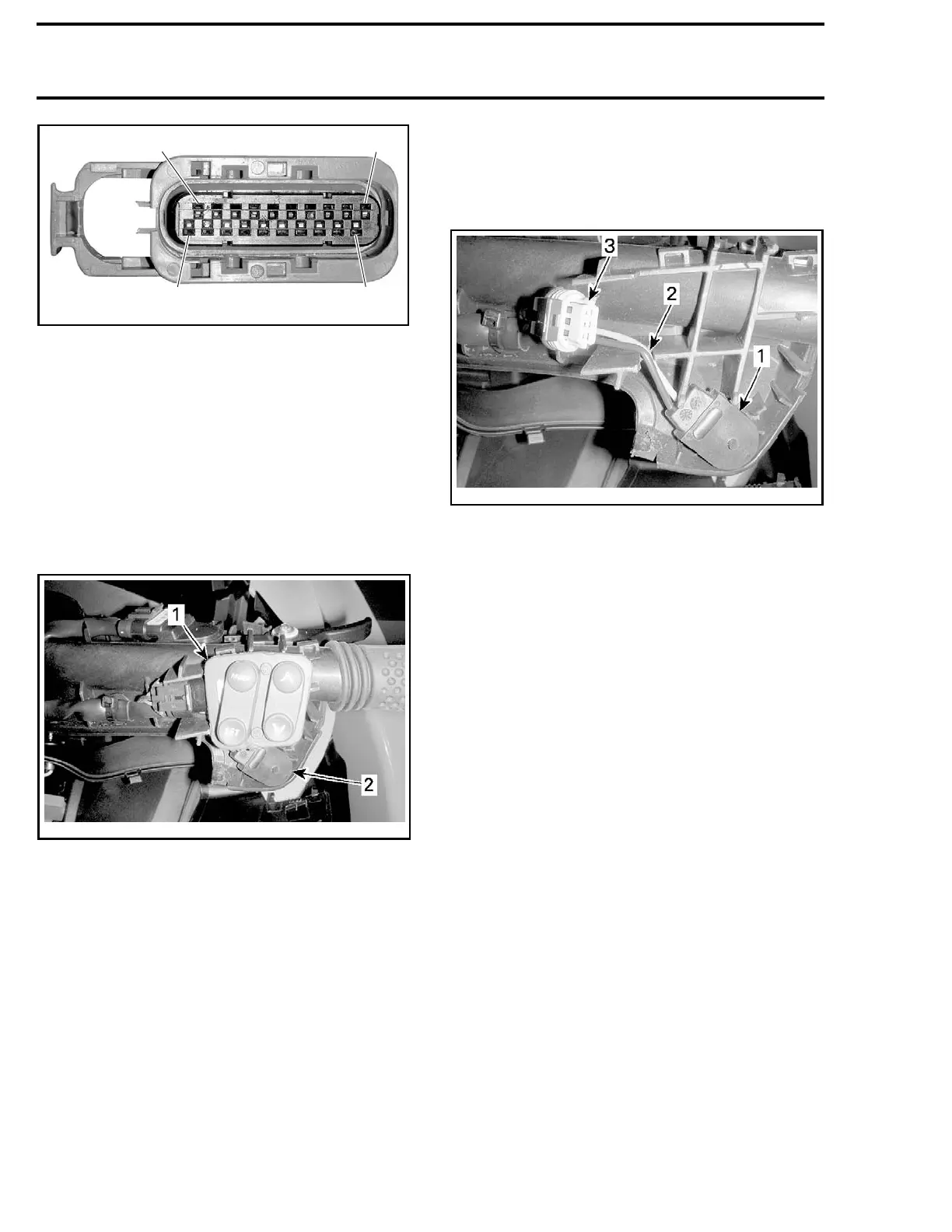
GAUGE CONNECTOR PIN-OUT
3. Attach a string approximately 1.2 m (4 ft) to the
end of the wires which will be used for draw-
ing the new switch wires through the harness
protective sheath.
4. Remove steering cover. Refer to
STEERING
AND O.T.A.S.
subsection.
5. Remove the MODE/SET and UP/DOWN arrow
switches from its support.
NOTE: It is not necessary to disconnect
switches.
smr2009-036-013_b
1. MODE/SET and UP/DOWN arrow switches
2. Cruise
switch
6. Remove the cruise switch by lifting it off its sup-
port.
7. Cut th
e locking ties from the harness sheath as
neces
sary.
8. Carefully pull the wires out of the harness.
Ensure the string draws through the harness
sheath.
9. Tie the string to the new cruise switch wire
ends and pull the new wires through the har-
ness.
10. Ins
tall new switch terminals in the gauge con-
nec
tor.
11. Apply a small amount of
DIELECTRIC GREASE
(P/N 293 550 004)
on switch terminals.
12. Reconnect gauge connector.
13. Properly insert cruise switch wiring in slot in
switch support before installing MODE/SET
and UP/DOWN arrow switches.
smr2009-036-014_a
SOME PARTS REMOVED FOR CLARITY
1. Cruise switch
2. Wiring in slot
3. MODE/SET and UP/DOWN arrow switch connector
14. Complete installation in reverse order of re-
moval.
218 smr2009-050

 Loading...

