Section 05 ELECTRICAL SYSTEM
Subsection 01 (CONTROLLER AREA NETWORK (CAN))
CAN Continuity Tests
If a communication problem is present, perform
the appropriate continuity test relating to the com-
ponent reported by B.U.D.S.
Test wire continuity between the corresponding
terminal of the CAN bus bar in fuse box no. 2 and
the suspected component as follows.
Remove cover from fuse box no. 2.
2009-027-009_a
1. Fuse box no. 1
2. Fuse box no
.2
Pull out both CAN bus bars.
smr2009-027-010_d
FUSE BOX #2
1. CAN LO bus bar
2. CAN HI bus bar
Inspect bus bar condition.
Disconnect the connector from the component to
be tested. Refer to its appropriate subsection.
Use the
FLUKE 115 MULTIMETER (P/N 529 035 868)
and select .
Refer to the
CAN BUS DIAGRAM
above and read
wire resistance between the proper bus bar termi-
nal and the component terminal. Check the con-
tinuity of the WHITE/RED wire and the continuity
of the WHITE/BLACK wire.
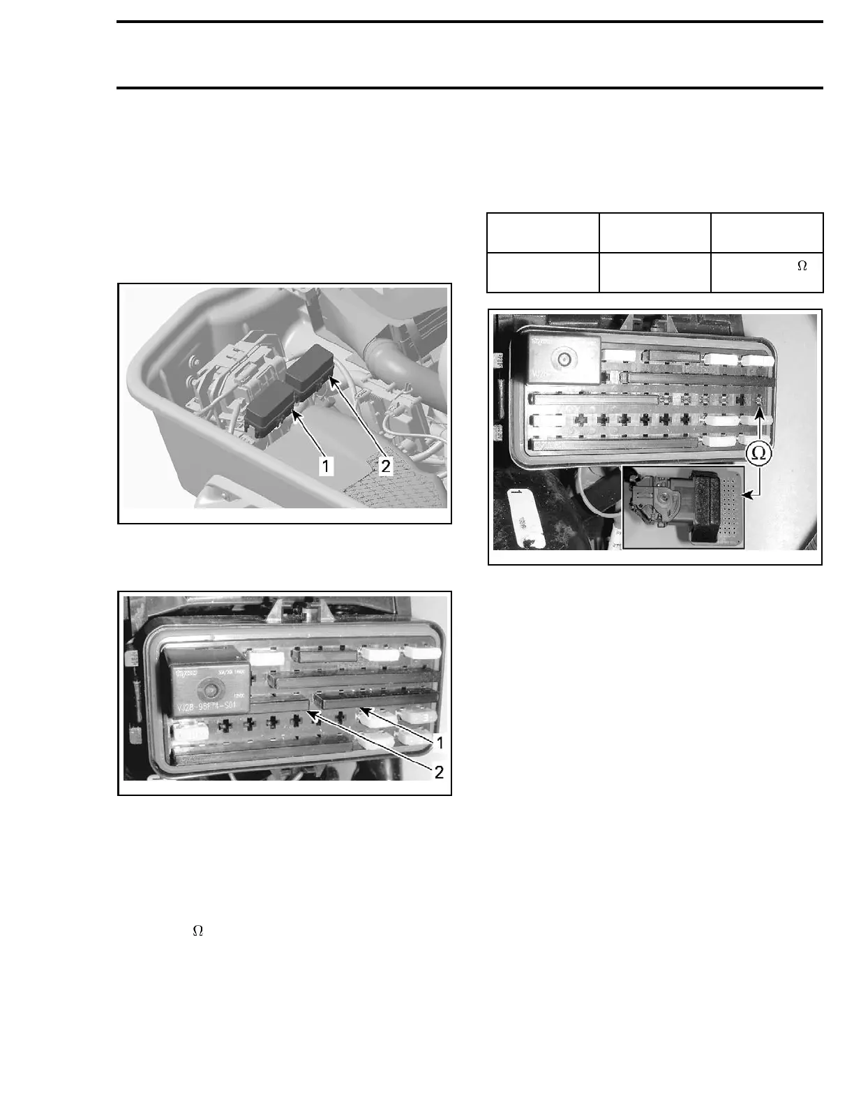
The following gives an example between the CAN
LO wire and the ECM.
NOTE: When working with the ECM, install the
ECM ADAPTER TOOL (P/N 529 036 166) on ECM "B"
connector.
ECM
CONNECTOR
FUSE BOX
TERMINAL
RESISTANCE
B-C2 FB2-C1
Closeto0
(continuity)
smr2009-
048-001_a
EXAMPLE CHECKING ECM CAN LO WIRE
If continuity is good, CAN lines are functional.
If continuity is not good, check wiring, connectors
and terminals condition.
NOTE: It m
ay be necessary to check the continu-
ity to mor
e than one component.
Reconnect connectors and reinstall removed
parts.
smr2009-048 279

 Loading...

