Assembly and Installation
FLOWSIC100 · Operating Instructions · 8012513/YSA5/V 2-1/2016-07 · © SICK Engineering GmbH 109
Subject to change without notice
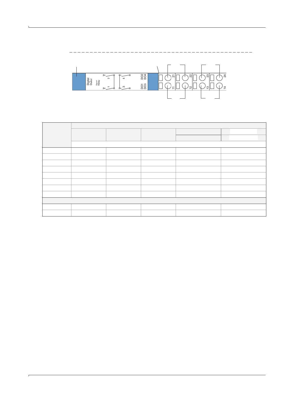
Terminal assignment DO module (4 NO contacts)
Fig. 81 Terminal assignment digital output module (4 NO contacts)
● Terminal data
n.c.: normal closed
n.o. normal open
n.o. com. com. n.o.
DO1 DO3
Digital output module Module carrier
DO2 DO4
n.o. com. com. n.o.
Connection Module type
2x analog input 2x analog output 2x digital input Digital output Digital output
2 changeover contacts 4 NO contacts
Assignment
11 AI 1+ AO 1+ DI 1+ n.c. relay 1
n.o. relay 1
12 AI 1- AO 1- gnd com. relay 1
com. relay 1
13 AI 2- AO 2- gnd com. relay 2
com. relay 3
14 Screen (gnd) Screen (gnd) DI 3+ n.c. relay 2
n.o. relay 3
21 AI 2+ AO 2+ DI 2+ n.o. relay 1
n.o. relay 2
22 AI 1- AO 1- gnd com. relay 1
com. relay 2
23 AI 2- AO 2- gnd com. relay 2
com. relay 4
24 Screen (gnd) Screen (gnd) DI 4+ n.o. relay 2
n.o. relay 4
Load
max. voltage 3 V DC 15 V DC 5.5 V DC 30 V AC/DC
24 V DV
max. current 22 mA 22 mA 5 mA 2 A
36 mA