Assembly and Installation
FLOWSIC100 · Operating Instructions · 8012513/YSA5/V2-1/2016-07 · © SICK Engineering GmbH 53
Subject to change without notice
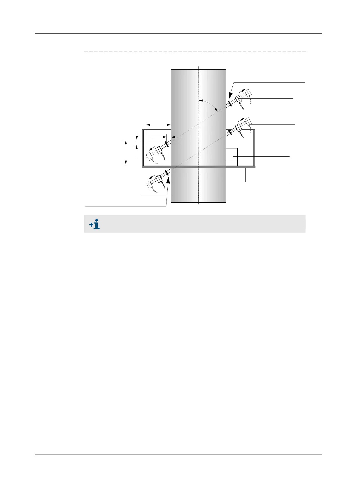
Fig. 27 Installing the sender/receiver units on a vertical duct
Select an installation angle of 60° for duct diameters as from approx. 4.5 m.
FLSE100 installed
below the platform
(with removable open-
ing and basket guard)
A = x + (NL+270) • sin
B = y + (NL+270) • cos
(NL = nominal length of FLSE100;
see
p. 17, 2.3.1)
Duct
A
Installation above platform
(attach platform if necessary)
FLSE100
*
FLSE100
withdrawn
Platform
Platform
or stage
a
y
* Type M shown here
x
B