Chapter 6 Operating instructions
S3000
102 © SICK AG • Industrial Safety Systems • Germany • All rights reserved 8009942/WK81/2012-11-28
Subject to change without notice
Electrical installation
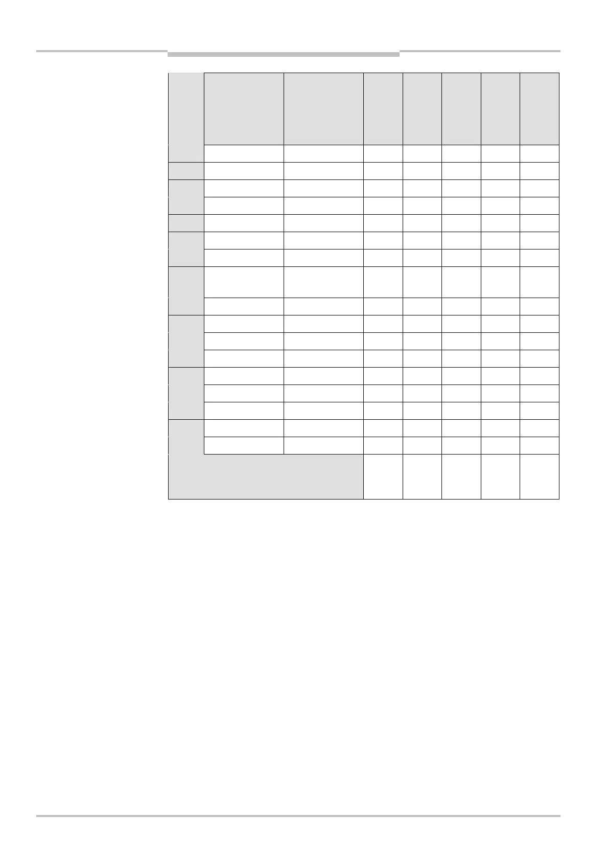
Pin Signal Wire color
SX0A-B0905G
SX0A-B0910B
SX0A-B0920B
SX0A-B1310B
SX0A-B1320B
SX0A-B1305D
SX0A-B1310D
SX0A-B1710B
SX0A-B1720B
1 +24 V DC Brown
2 0 V DC Blue
3 OSSD1 Gray
4 OSSD2 Pink
5 RESET Red
6 EDM Yellow
7UNI<I/O1/ERR White/black
8 UNI<I/O2/
RES_REQ
Red/blue
9 UNI<I/O3/WF White/brown
10 A1 White/red
11 A2 White/orange
12 B1 White/yellow
13 B2 White/green
18 C1 or INC1_0 White/blue
19 D1 or INC1_90 White/gray
22 C2 or INC2_0 White/purple
23 D2 or INC2_90 White
Number of top mounted cable glands
(cable entries to the rear sealed with
blanking plugs)
22242
Disconnect all cores from the system plug that are not necessary for the related
application! (in this way you will prevent possible interference.)
pre>assembled system plug
Note