Operating instructions Chapter 3
S3000
8009942/WK81/2012-11-28 © SICK AG • Industrial Safety Systems • Germany • All rights reserved 27
Subject to change without notice
Product description
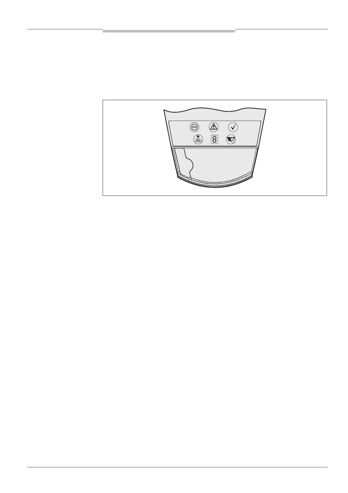
3.4 Status indicators
3.4.1 LEDs and 7@segment display
The LEDs and the 7<segment display indicate the operational status of the S3000. They
are positioned on the front of the safety laser scanner. Above the LEDs there are symbols
that are used in the remainder of these operating instructions to describe the LEDs.
The symbols have the following meaning:
OSSDs in the OFF state (e.g. on object in the protective field, reset required, lock-out)
Warning field interrupted (object in the warning field or in one of the warning fields)
OSSDs in the ON state (no object in protective field)
Reset required
Front screen contaminated
7<segment display for the indication of the status and errors
You will find detailed information in section 11.3 “Error and status indications on the
LEDs” on page 133 and in section 11.4 “Error and status indications on the 7< segment
display” on page 135.
the S3000
Note