Chapter 4 Operating instructions
S3000
44 © SICK AG • Industrial Safety Systems • Germany • All rights reserved 8009942/WK81/2012-11-28
Subject to change without notice
Configurable functions
4.5.1 Input delay
If the control device via which you switch the static control inputs cannot switch within
10 ms (for 60 ms basic response time) or 20 ms (for 120 ms basic response time) to the
related input condition (e.g. due to switch bounce times), you must configure an input
delay. For the input delay choose the time in which your defined control device can switch
to a corresponding input condition.
Independent of the basic response time chosen for the S3000, you can increase the input
delay in 30-ms steps (for 60 ms basic response time) or 60-ms steps (for 120 ms basic
response time).
The following figures, based on experience, give input delays for various methods of
switching:
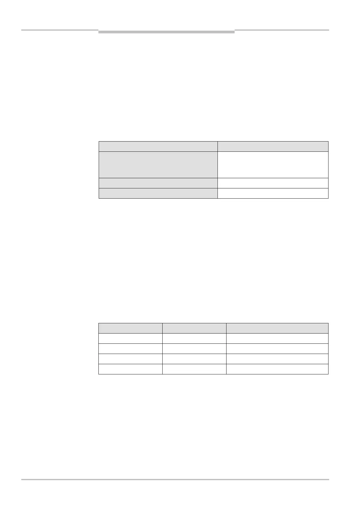
Switching method Input delay required
Electronic switching using controller or
complementary electronic outputs with
0 to 10 ms bounce time
10 ms
Contact (relay) controls 30-150 ms
Control using independent sensors 130-480 ms
Also pay attention to the notes in section 5.6 “Time for monitoring case switching” on
page 86.
4.5.2 Sampling for the static control inputs
If you are using static sampling, decide between complementary or 1<of<n sampling
depending on the control features available. Depending on this selection you can define
the switching criteria for the monitoring cases (see section 4.10.1 “Monitoring case
switching via static input information” on page 58).
Complementary sampling
One control input comprises two connections. For correct switching one connection must
be inverted in relation to the other.
The following table shows the levels that must be present at the connections for the
control input to define the logical input state 1 and 0 at the related control input.
A1 A2 Logical input state
10 0
01 1
11 Error
00 Error
experience for the necessary
input delay
Note
connections for the control
inputs for complementary
sampling