Operating instructions Chapter 6
S3000
8009942/WK81/2012-11-28 © SICK AG • Industrial Safety Systems • Germany • All rights reserved 99
Subject to change without notice
Electrical installation
EFI systems
Connect EFI-A on the first device with EFI-A on the second device and EFI-B on the first
d
evice with EFI-B on the second device.
Always use screened twisted pair cables!
If the length of the cable to the safety laser scanner is more than 30 m, the shield is to
b
e connected as close as possible to the device.
In an EFI system with two safety laser scanners, set the address of one of the scanners
to guest!
To differentiate unambiguously between the host and guest device in an EFI system, one
S3000 must be configured as the guest. For this purpose a jumper is wired between the
connection terminals 7 (ERR) and 10 (A1).
The jumper always defines the guest device. This jumper is never allowed to be fitted on
the host device.
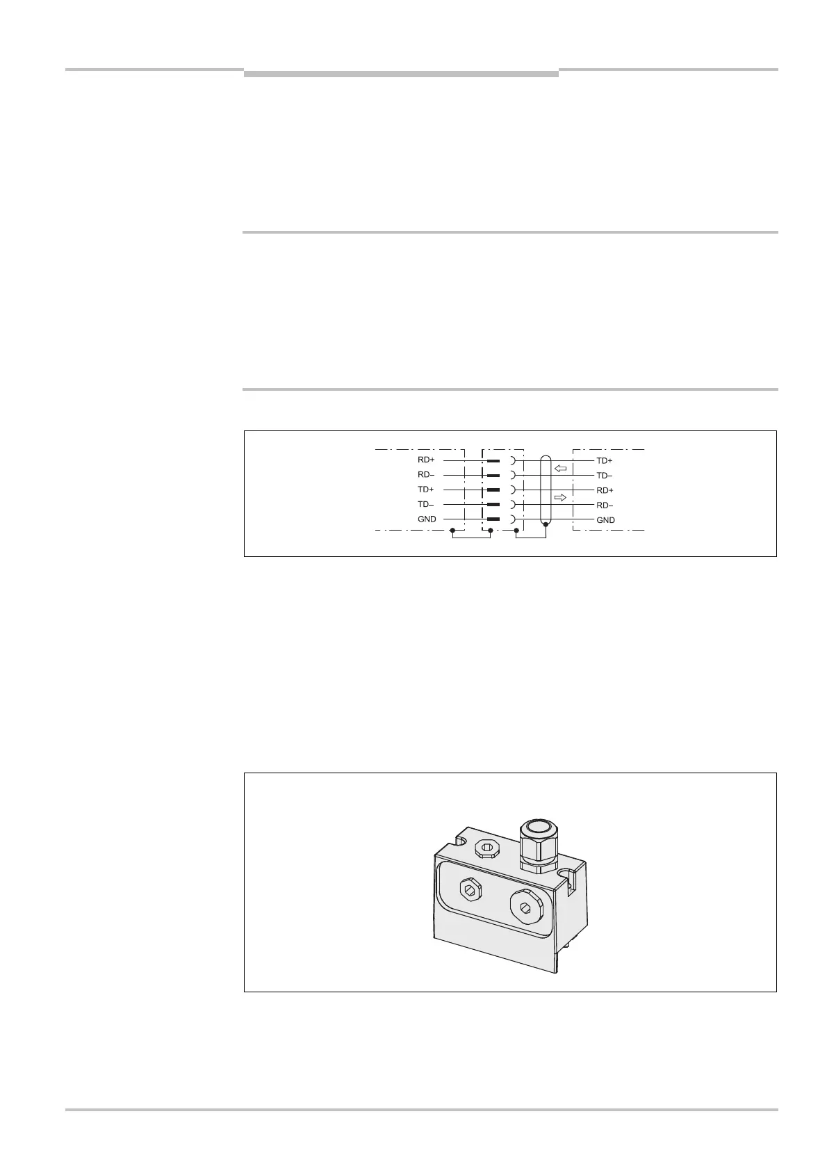
RS-422 interface
6.2 System plug assembly
The system plug has holes on the top and rear. Suitable cable entries for these holes are
included with the device. The number of cable entries varies (see also section 13.3.4
“System plug” on page 164):
system plug SX0A-A0000B:
– 1 cable entry without M12 cable gland (blanking plug)
– 1 cable entry with M20 cable gland
– 2 blanking plugs for the unused outlets
Notes
WARNING
RS-422 interface
SX0A>A0000B
rear