Operating instructions Chapter 11
S3000
8009942/WK81/2012-11-28 © SICK AG • Industrial Safety Systems • Germany • All rights reserved 133
Subject to change without notice
Diagnostics
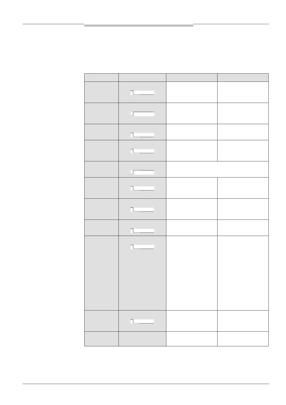
11.3 Error and status indications on the LEDs
T
his section describes the meaning of the error and status indications of the LEDs and
how you can respond. You will find a description of the indicators in section 3.4 “Status
indicators” on page 27, the connections for the outputs in section 6.1 “System
c
onnection” on page 96.
Display Output level Possible cause Rectification of the error
At the OSSDs Object in the protective
field, OSSDs in the OFF
state
No error
At the OSSDs Protective field
unoccupied,
OSSDs in ON state
No error
On the universal I/O
23)
Object in warning
field
24)
No error
OSSDs No operating voltage,
or voltage too low
Check the voltage
supply and activate,
if necessary.
On the universal I/O
25)
No error
On the universal I/O
25)
No supply voltage Check the voltage
supply and activate,
if necessary.
On the universal I/O
25)
Front screen contami-
nated, operation not
guaranteed
Clean the front
screen.
On the universal I/O
25)
Front screen contami-
nated, still in operation
Clean the front
screen.
On the universal I/O
25)
System error Pay attention to the
error display of the
7<segment display or
carry out a diagno-
stics with the aid of
the CDS.
Switch off the vol-
tage supply for the
S3000 for at least
2 seconds and then
switch it back on.
On the universal I/O
26)
Reset required Operate the control
switch for restart or
reset.
No level change Restart delay is
counting down
No action is required
23)
If this is configured as warning field output.
24)
On the S3000 in the triple field mode, the 7<segment display shows which warning field contains an object.
25)
If this is configured as the output for a contamination error/warning.
26)
If this is configured as the output for “Reset required”.
indications on the LEDs