Chapter 5 Operating instructions
S3000
88 © SICK AG • Industrial Safety Systems • Germany • All rights reserved 8009942/WK81/2012-11-28
Subject to change without notice
Mounting
5.7 Mounting steps
S
pecial features to note during mounting:
Mount the S3000 such that it is protected from moisture, dirt and damage.
Ensure that the entire field of view of the S3000 is not restricted.
Mount the safety laser scanner such that the indicators are easy to see.
Always mount the S3000 such that you can plug in and remove the system plug.
Avoid excessive shock and vibration loading on the safety laser scanner.
On systems that suffer from heavy vibration, prevent the fixing screws from coming loose
using screw locking devices.
Regularly check the tightness of the fixing screws.
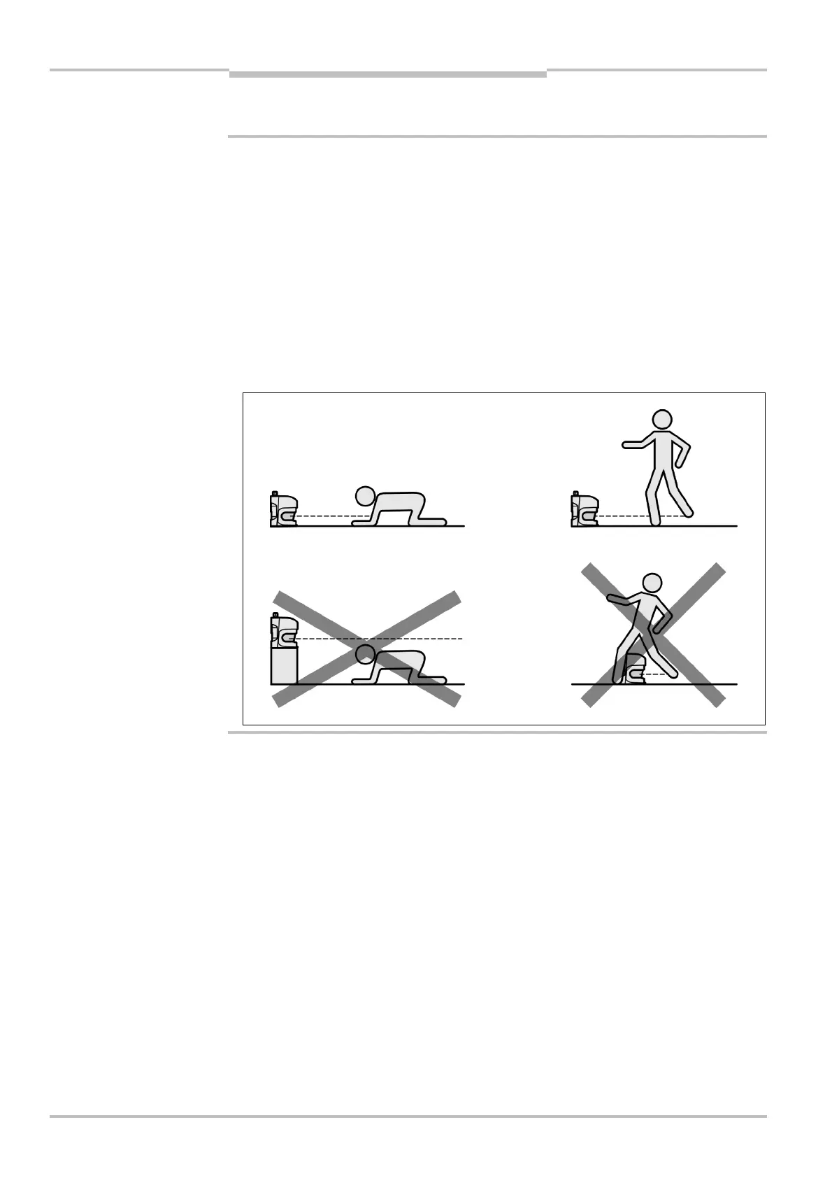
Prevent personnel from being able to crawl beneath, stand behind or climb over the
protective field by means of appropriate mounting of the S3000.
The origin of the scan plane is 63 mm above the bottom edge of the S3000. If you mount
the S3000 using mounting kit 3, then the origin of the scan plane is 102 mm above the
bottom edge of mounting kit 3 (see section 12.6.3 “Scan plane origin” on page 161).
There are four possible ways of mounting the S3000:
direct mounting without mounting kit
mounting with mounting kit 1
mounting with mounting kit 1 and 2
mounting with mounting kit 1, 2, and 3
The mounting kits build one on another. For mounting with mounting kit 2 you will
therefore also need mounting kit 1. For mounting with mounting kit 3 you will therefore
also need mounting kits 1 and 2. You will find the part numbers for the mounting kits in
section 13.3.3 “Mounting kits” on page 163.
WARNING
beneath, standing behind,
climbing over