Chapter 6 Operating instructions
S3000
98 © SICK AG • Industrial Safety Systems • Germany • All rights reserved 8009942/WK81/2012-11-28
Subject to change without notice
Electrical installation
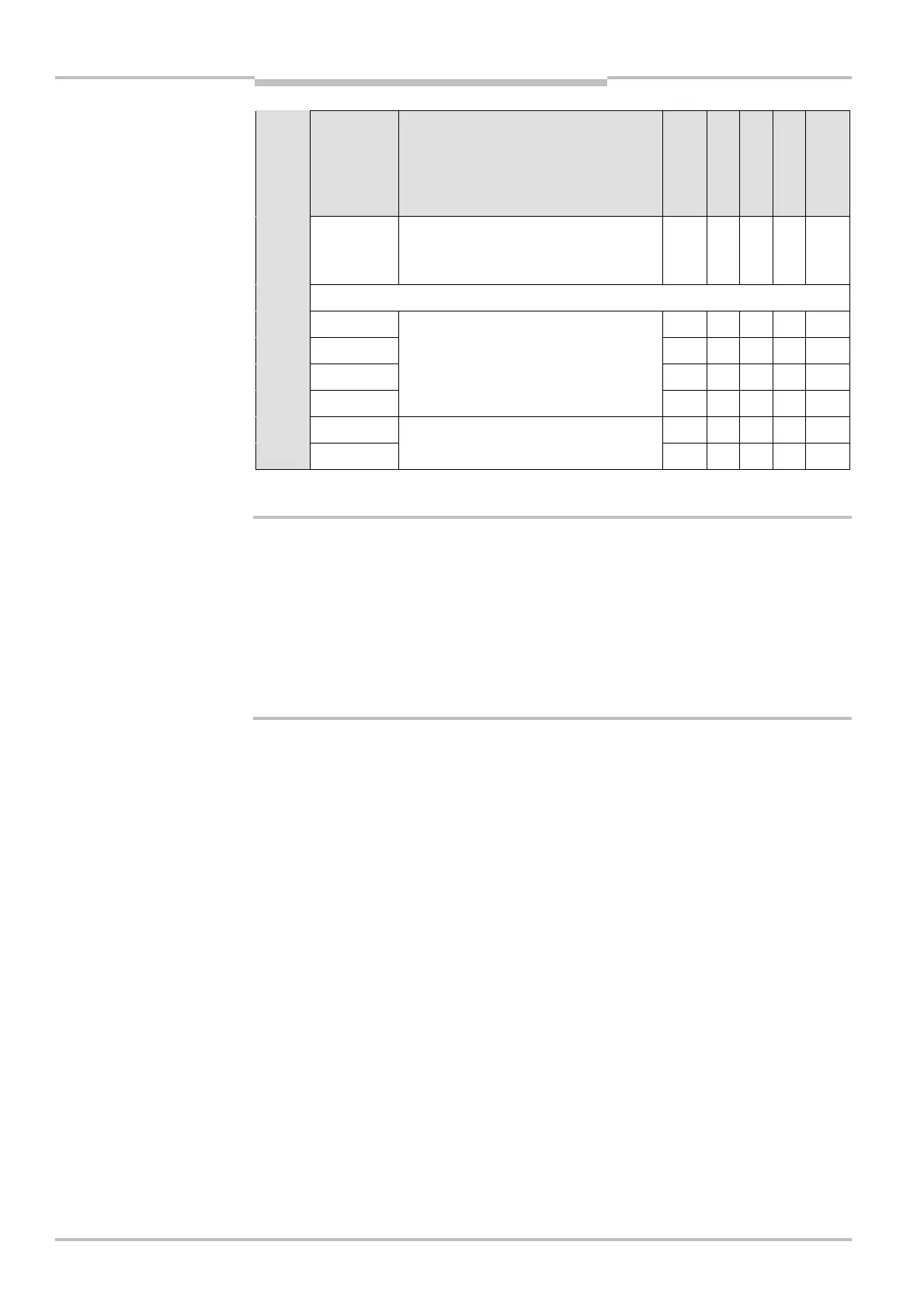
Pin Signal Function
Standard
Advanced
Professional
Expert
Remote
23 D2 or
INC2_90
Static control input D or dynamic
control input (incremental encoder
input) 2
24 Reserved, do not use!
25 RxD–
26 RxD+
27 TxD+
28 TxD–
RS<422 interface for output of
measured data
29 EFI
A
30 EFI
B
Enhanced function interface =
safe SICK device communication
Incremental encoder specification
Never supply both incremental encoders using one supply cable!
The connection cables for the incremental encoders must each be in a separate plastic-
sheathed cable as otherwise a cable break could cause an error that could remain
undetected.
The power supply to the two incremental encoders must be independent. For this
purpose use the connection terminals provided, 16 and 17 as well as 20 and 21.
Each incremental encoder output (for 0° or 90°) is only allowed to be connected to one
control input, e.g. C1/D1 or C2/D2.
Both incremental encoders must meet the following specifications:
two-channel rotary encoder with 90° phase offset
supply voltage: 24 V DC
outputs: push/pull outputs
enclosure rating IP 54 or better
screened cable
max. pulse frequency: 100 kHz
min. number of pulses: 50 pulses per cm
You can procure suitable incremental encoders from SICK AG, tel.: +49 211/5301-250 or
at www.sick.com. Or contact your local SICK representative.
Control inputs
You can only connect the input signals to one safety laser scanner. Distributed connection
of the input signals to two safety laser scanners is not possible.
WARNING
Recommendation