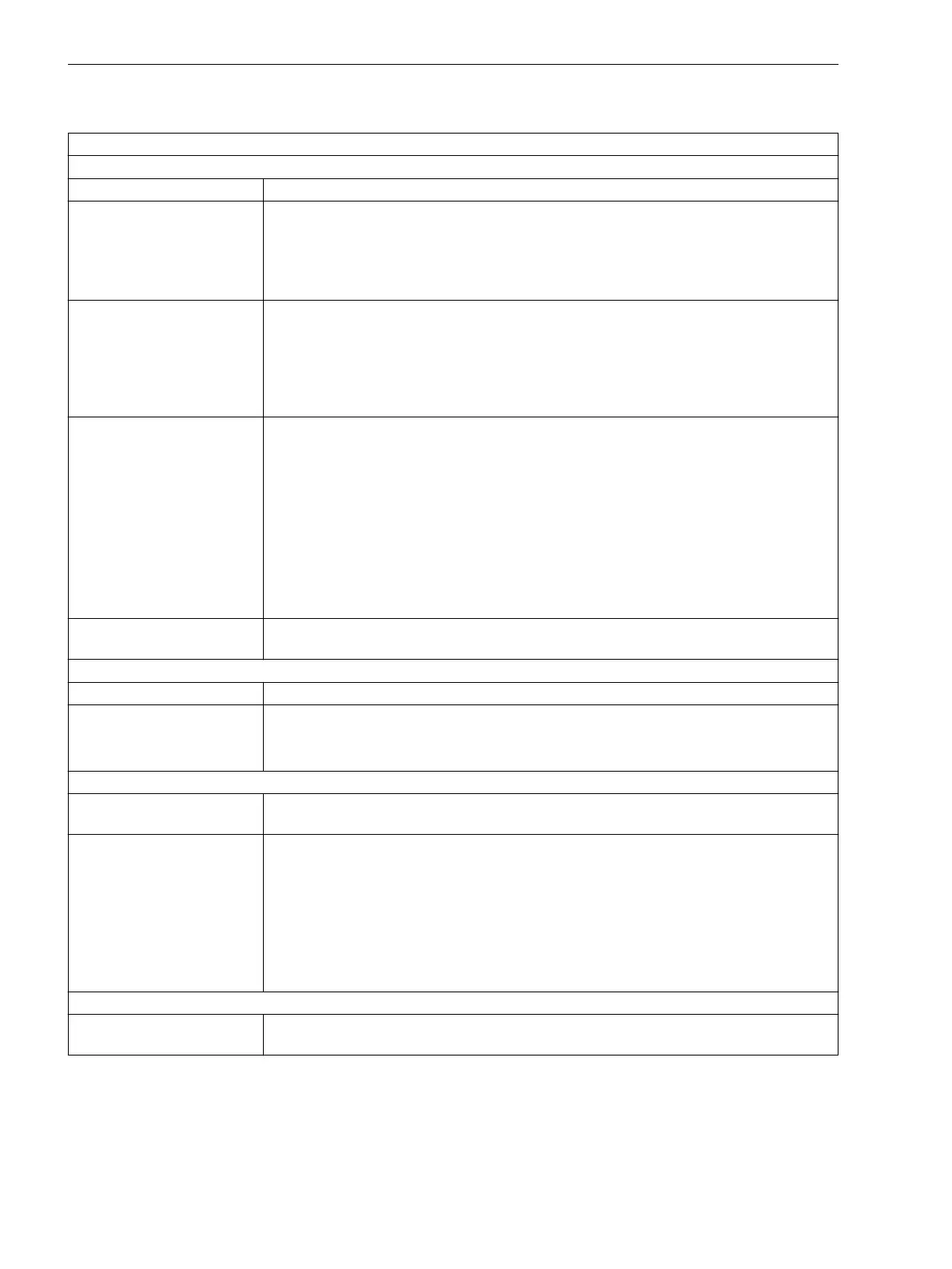
Table 2-24 Parameter in the Setting Dialog "Measurement Procedure", Mode of Operation 3-phase
Parameter OPERRAT. MODE = 3-phase
Parameter MEAS. QUANTITY = Current, Voltage or Voltage Side2
Parameter MEAS. METHOD
Fundamental
Only the fundamental harmonic is evaluated, higher harmonics are suppressed. This is
the standard measurement procedure of the protection functions.
Important: The voltage threshold value is always parameterized as phase-to-phase
voltage. If parameter VOLTAGE SYSTEM is selected as phase-to-ground, the voltage
threshold will be devided by √3.
True RMS
The "true" RMS value is determined, i.e. higher harmonics are evaluated. This procedure is
applied, for example, if an overload protection element must be realized on the basis of a
current measurement, as the higher harmonics contribute to thermal heating.
Important: The voltage threshold value is always parameterized as phase-to-phase
voltage. If parameter VOLTAGE SYSTEM is selected as phase-to-ground, the voltage
threshold will be devided by √3.
Positive seq.,
Negative seq.,
Zero sequence
In order to realize certain applications, the positive sequence system or negative
sequence system can be configured as measurement procedure. Examples are:
- I2 (Negative sequence protection)
- U2 (Voltage asymmetry)
Via the selection zero sequence system, additional zero sequence current or zero
sequence voltage functions can be realized that operate independent of the ground varia-
bles IN and VN, which are measured directly via transformers.
Important: The voltage threshold is always parameterized according to the definition of
the balanced components independently of parameter VOLTAGE SYSTEM.
Difference to the funda-
mental component
The setting Delta value activates the jump detection. For more information, see
Section 2.19 Flexible Protection Functions at Jump Detection.
Parameter MEAS. QUANTITY = Current
Parameter MEAS. METHOD
Ratio I2/I1
The ratio of the negative-sequence current to the positive-sequence current is evaluated.
Please note that the function only operates if Ι2 or Ι1 has exceeded the threshold value
0.1 · Ι
Nom
.
Parameter MEAS. QUANTITY = Voltage
Parameter VOLTAGE
SYSTEM
Phase-Phase
Phase-Ground
If you have configured address 213 VT Connect. 3ph to Van, Vbn, Vcn or Vab,
Vbc, VGnd, you can select whether a three-phase voltage function will evaluate the
phase-to-ground voltage or the phase-to-phase voltages.
When selecting phase-to-phase, these variables are derived from the phase-to-ground
voltages. The selection is, for example, important for single-pole faults. If the faulty
voltage drops to zero, the affected phase-to-ground voltage is thus zero, and the respec-
tive phase-to-phase voltages drop to the variable of a phase-to-ground voltage.
With phase-to-phase voltage connection, the parameter is hidden.
Parameter MEAS. QUANTITY = Voltage Side2
Parameter VOLTAGE
SYSTEM
Functions
2.19 Flexible Protection Functions
330 SIPROTEC Compact, 7SC80, Manual
E50417-G1140-C486-A8, Edition 07.2017



 To Next Page