CPU and Input/Output Configuration
6-6
S7-200 Programmable Controller System Manual
A5E00066097-02
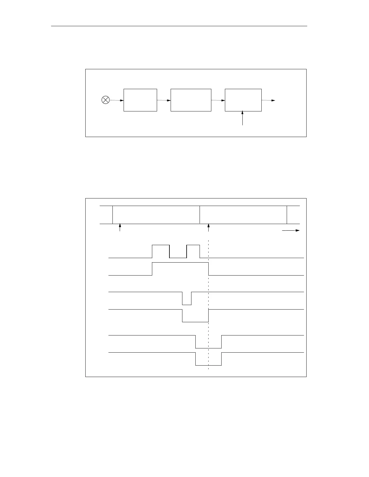
A block diagram of the digital input circuit is shown in Figure 6-5.
Optical
isolation
Digital input
filter
Pulse catch
function
Pulse catch
enable
External
digital input
Input to CPU
Figure 6-5 Digital Input Circuit
The response of an enabled pulse catch function to various input conditions is
shown in Figure 6-6. If you have more than one pulse in a given scan, only the first
pulse is read. If you have multiple pulses in a given scan, you should use the I/O
interrupt described in Section 9.15.
Input to
pulse catch
Output from
pulse catch
Input to
pulse catch
Input to
pulse catch
Input update Input update
CPU scan n+1CPU scan n
Time
Output from
pulse catch
Output from
pulse catch
Figure 6-6 Pulse Catch Example

 Loading...


