Using USS Protocol Instructions to Communicate with Drives
11-22
S7-200 Programmable Controller System Manual
A5E00066097-02
NETWORK 1 // Initialize USS Protocol
//
LD SM0.1 //On the first scan
CALL USS_INIT, 1, 19200, 16#1, Q0.0, VB1
//Enable the USS protocol for port 0 at 19200 baud
//with drive address “0” active.
NETWORK 2 //Control box for drive 0
//
LD SM0.0
CALL DRV_CTRL, I0.0, I0.1, I0.2, I0.3, I0.4, 0, 100.0, M0.0, VB2, VW4,
VD6, Q0.0, Q0.1, Q0.2, Q0.3
NETWORK 3 Read a parameter from drive 0
//
LD I0.5
= L60.0 //Save the state of I0.1 to a temporary L location so that
//this network will display in LAD.
LD I0.5
EU
= L63.7 //Save the rising edge pulse of I0.2 to a temporary L
//location to that it can be passed to the CW subroutine.
LD 60.0
CALL READ_PM, L63.7, 0, 5, &VB20, M0.1, VB10, VW12
1
2
3
4
5
6
7
8
9
10
11
12
13
14
15
16
17
18
19
20
21
22
23
24
25
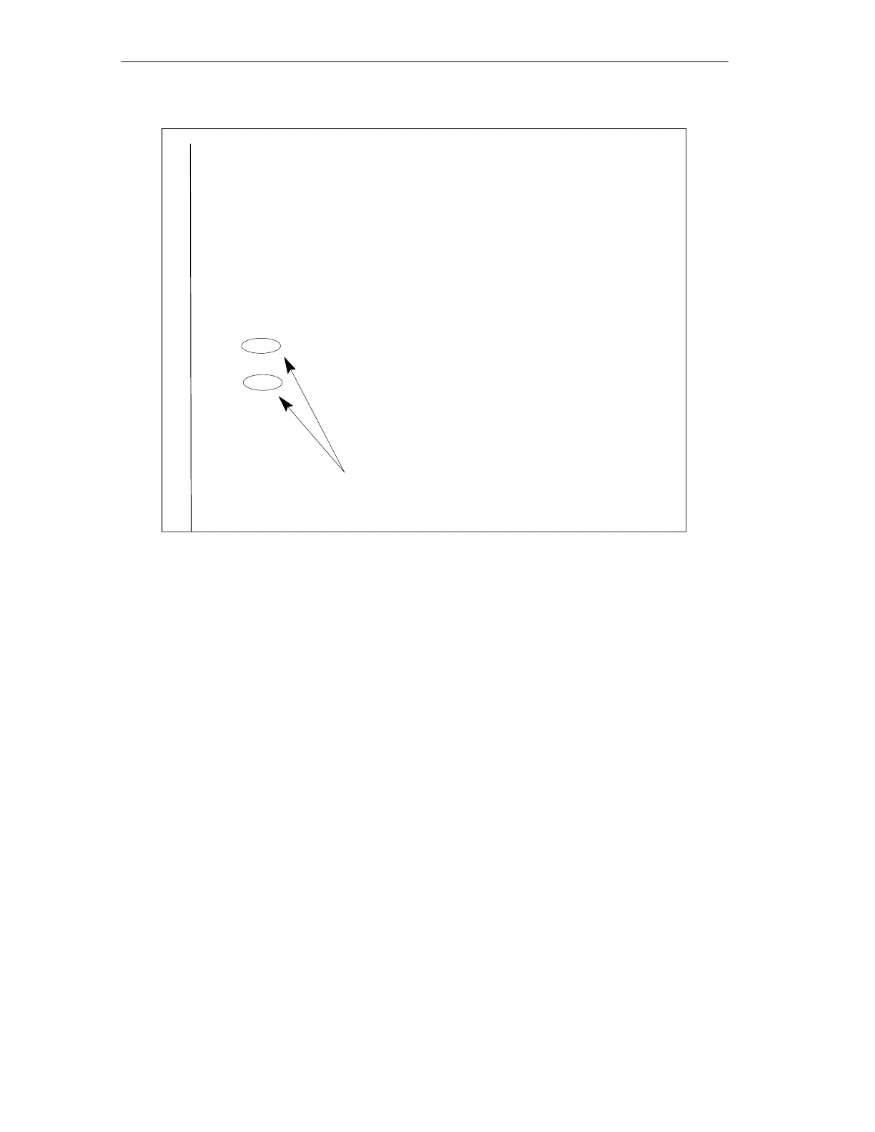
These two contacts must be the same.
Figure 11-11 Example of USS Instructions for SIMATIC STL

 Loading...


